By Wu Peng, Senior Process Instrumentation Engineer · Last reviewed July 21, 2026
Pressure and temperature compensation corrects a gas or steam flow reading for the density change that happens whenever line pressure or temperature moves away from the values the meter was sized for. A volumetric meter reports how much space the gas occupies at line conditions. Compensation converts that into mass flow or standard volume. Those are the quantities a boiler log, an energy bill, or a material balance actually needs.
The error is not small. On a vortex meter, running 1 bar above the assumed pressure understates standard flow by about 12.5 percent. This guide gives the compensation formulas for both differential pressure (DP) and velocity meters, three worked calculations, the saturated steam shortcut, and the instrumentation that does the math for you.
Contents
- Why compensation matters
- The compensation formulas
- Worked examples
- Saturated steam rules
- Standard reference conditions
- Real gas corrections
- Choosing the instrumentation
- FAQ
Why compensation matters
Liquids are nearly incompressible, so a liter of water is the same amount of water at 2 bar or at 8 bar. Gases and steam are different. Compress a gas to twice the absolute pressure and the same mass fits in half the volume; heat it and it expands. Orifice plates, vortex meters, and turbine meters all read volume at line conditions. None of them can tell the difference between more molecules and the same molecules squeezed tighter.
Flow elements are sized for one design condition: a stated pressure, temperature, and density. The plant never holds those values exactly. Boiler pressure swings with load, compressor discharge temperature climbs through the afternoon, and header pressure sags when a second line comes online. Every one of those swings shifts gas density, and the raw meter reading drifts with it while the transmitter sees nothing wrong. Compensation measures the actual pressure and temperature, recalculates density, and corrects the flow output in real time. The relationship between the DP signal and flow itself is covered in our guide to flow rate and pressure.
The compensation formulas
Two rules before any formula: work in absolute pressure, not gauge (see absolute vs gauge pressure), and work in absolute temperature, kelvin or rankine. Feeding 25 °C instead of 298.15 K into a compensation block is the single most common commissioning mistake we see.
For a velocity type meter (vortex, turbine, ultrasonic) that reports actual volume flow, the ideal gas correction to standard volume is linear:
Qs = Qa × (Pa / Ps) × (Ts / Ta)
where Qa is actual volume flow, P and T are absolute, subscript a is actual line condition and subscript s is the standard reference condition. Double the absolute pressure and the standard flow doubles.
A DP element behaves differently because the differential pressure already contains one density term. For a fixed orifice bore with the transmitter scaled in mass or standard volume units at design conditions, the correction carries a square root:
Qtrue = Qindicated × sqrt( (Pa × Td) / (Pd × Ta) )
where subscript d is the design condition from the sizing sheet. Note the direction: higher actual pressure means denser gas, so the same DP signal represents more mass than the uncompensated reading shows. The square root also means a DP meter is only half as sensitive to condition errors as a velocity meter, as the table below shows.
| Condition error | Velocity meter (linear) | DP meter (square root) |
|---|---|---|
| Temperature 15 K high at 300 K | 5.0% flow error | 2.5% flow error |
| Pressure 1 bar high at 6 bar g | 12.5% flow error | 6.4% flow error |
Errors in the reported standard or mass flow if the condition change is not compensated, relative to the true flow. Ideal gas, composition constant.
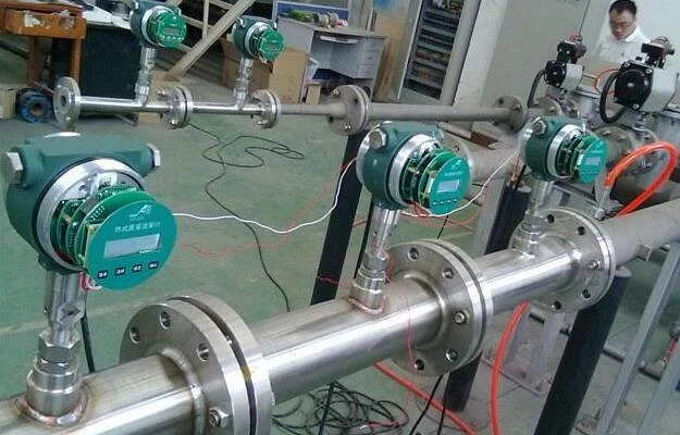
Standard arrangement: pressure tap upstream, temperature sensor downstream of the element so the thermowell does not disturb the velocity profile at the meter.
Worked examples
Example 1, vortex meter on compressed air. A vortex meter reads 500 m³/h actual volume at 7 bar g and 45 °C. Site barometric pressure is 101.3 kPa, so absolute pressure is 801.3 kPa and absolute temperature is 318.15 K. Referred to normal conditions (101.325 kPa, 0 °C = 273.15 K):
Qn = 500 × (801.3 / 101.325) × (273.15 / 318.15) = 3,395 Nm³/h
The correction factor is 6.79. Report that line as 500 m³/h and the compressed air balance comes up short by a factor of nearly seven.
Example 2, orifice on process gas. An orifice run was sized at 6 bar absolute and 15 °C (288.15 K). Today the line runs at 5 bar absolute and 30 °C (303.15 K), and the uncompensated transmitter indicates 10,000 Sm³/h. The true flow:
Q = 10,000 × sqrt( (5 × 288.15) / (6 × 303.15) ) = 10,000 × 0.890 = 8,900 Sm³/h
The uncompensated reading is 12 percent above the true flow, an overbilling error removed by two extra transmitters and one calculation block.
Example 3, how big is a temperature drift alone. A gas line sized at 300 K creeps up to 315 K on a summer afternoon. A vortex meter with no compensation now overstates standard flow by 315/300 = 1.05, a flat 5 percent. The same drift through an orifice square root is sqrt(315/300) = 1.025, about 2.5 percent. Small drifts matter at billing points and stay invisible on a trend screen.
Saturated steam rules
Saturated steam is the special case where you get one measurement free. On the saturation curve, pressure and temperature are locked together: 7 bar g saturated steam is always about 170 °C. So a saturated steam meter needs only one live input, pressure or temperature, and the density follows from the steam tables. Pressure is the better choice because it responds in milliseconds while a thermowell takes seconds to catch up.
| Service | Live inputs needed | Density source |
|---|---|---|
| Saturated steam | P or T (P preferred) | Steam table lookup |
| Superheated steam | P and T | Steam table, two variables |
| Gas, stable composition | P and T | Ideal gas or Z-corrected |
| Gas, variable composition | P, T and molecular weight | AGA8 or analyzer input |
| Liquids | Usually none; T for custody | Density vs temperature curve |
Superheated steam has left the saturation curve, so pressure and temperature move independently and both must be measured. A boiler header that swings between saturated and lightly superheated is the worst case; configure the computer for superheated service so it degrades gracefully. Our steam vortex flow meter integrates the temperature sensor and computer in one body for exactly this service, and the wider options are compared in the steam flow meter overview.
Standard reference conditions
Compensated flow is always referred to a standard condition, and there is more than one standard. Normal cubic meters (Nm³) use 0 °C and 101.325 kPa. Standard cubic meters (Sm³) commonly use 15 °C. American SCF tables usually sit at 60 °F. The difference between 0 °C and 15 °C references alone is 5.5 percent, larger than the accuracy class of most gas meters. Always write the reference condition next to the unit on datasheets and contracts. The full unit landscape is covered in our flow rate units guide, and the volumetric versus mass distinction in mass flow rate vs volumetric flow rate.
Real gas corrections
The formulas above assume ideal gas behavior. Real gases deviate by the compressibility factor Z, which itself changes with pressure and temperature. For air, nitrogen, and hydrogen near ambient conditions the deviation is under a percent and ideal gas math is fine. For natural gas at pipeline pressure, CO2, or any hydrocarbon near its dew point, Z moves several percent. The compensation computer should then run a real gas equation. AGA8 and SGERG are the standard methods for natural gas, and custody codes require them. If composition also varies, a molecular weight input from an analyzer completes the density calculation. When the correction chain grows that long, it is often cheaper to measure mass directly with a Coriolis mass flow meter or a thermal mass flow meter, neither of which needs PT compensation at all.
Choosing the instrumentation
Compensation can live in four places: a multivariable transmitter, the flow meter itself, a dedicated flow computer, or the DCS. The right answer depends on how many signals you want to run and who maintains the math.
| Approach | How it works | Typical service |
|---|---|---|
| Multivariable DP transmitter | One device measures DP, P and T and outputs compensated mass flow | Orifice and averaging pitot runs; see DP transmitters |
| Meter with built-in PT | Vortex or gas meter carries its own P and T sensors | Steam vortex, gas rotameter, gas turbine meter |
| External flow computer | Separate P and T transmitters wired to a corrector or DCS block | Custody skids, rotary gas meters with correctors, retrofits |
| Direct mass meter | Coriolis or thermal measures mass, no compensation needed | Variable composition, high accuracy, compressed air audits |
Retrofits are common: an existing orifice run keeps its element, gains a pressure and a temperature transmitter, and the DCS does the arithmetic. Verify the compensation block against a hand calculation at commissioning. We have seen the pressure ratio entered upside down more than once. The meter then drifts in the wrong direction with every load change.
Application example
Municipal water utility, Serbia. The utility asked for 0.2 percent accuracy on a steam line, tighter than any vortex meter class delivers. The larger error source, though, was uncompensated density: normal steam pressure swings shift an uncompensated reading by more than any nameplate accuracy figure. The quoted setup paired a vortex flow meter with separate pressure and temperature transmitters for PT compensation, with the transmitter remote-mounted on 25 m of cable away from the hot line. With compensated mass flow doing the real accuracy work, the customer accepted the stated 1.5 percent class.
Gas moisture is stated on the same pressure-referenced basis; the dew point measurement guide walks through pressure dew point.
Which of the two inputs a steam line needs depends on its state, which is covered in saturated vs superheated steam.
FAQ
What is temperature compensation for flow measurement?
Temperature compensation measures the actual fluid temperature and corrects the flow reading for the density change that temperature causes. In gases the correction follows the absolute temperature ratio Ts/Ta; in liquids it is a small density adjustment used mainly in custody transfer.
What is the difference between compensated and uncompensated flow meters?
An uncompensated meter reports volume at line conditions, so its reading drifts whenever pressure or temperature moves away from the sizing values. A compensated meter adds live pressure and temperature inputs and outputs mass or standard volume, which stays correct as conditions swing. For gas and steam the difference routinely reaches 5 to 15 percent.
Why is pressure and temperature compensation required for orifice flow measurement?
The orifice DP signal depends on gas density as well as flow. When line pressure or temperature departs from the sizing sheet, density changes and the transmitter converts DP to flow using the wrong density. Compensation restores the true value through the square root correction shown above, halving the sensitivity but not removing it.
What is temperature compensation in magnetic flow meter?
Magnetic flow meters measure liquid velocity and are essentially immune to pressure and temperature effects on the reading itself, so they do not use PT compensation. Temperature only matters when you convert the volume total to mass for a liquid whose density shifts with temperature, and that correction happens in the DCS, not the meter.
Request a quote
Tell us the fluid, line size, pressure and temperature range, and whether you need mass flow or standard volume, and we will propose a compensated metering setup: multivariable DP, vortex with integral PT, or a direct mass meter. Tell us the application and we configure one unit, not a shelf part. Reach our application engineers or use the form below.
Written and technically reviewed by Wu Peng and the Instranova engineering team.