By Wu Peng, Senior Process Instrumentation Engineer · Last reviewed September 4, 2026
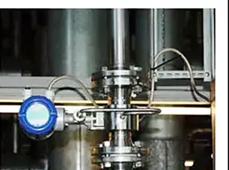
Most flow meters can be installed on a vertical pipe. For liquids the rule is short: the flow must travel upward, from bottom to top. Upward flow keeps the meter full, carries bubbles and solids through instead of letting them collect, and costs little or no accuracy.
The exceptions sit at the two ends of the spectrum. Variable area meters must be vertical by design, while downward liquid flow is the one arrangement almost every manufacturer warns against.
This guide gives the vertical flow meter installation rules meter by meter: magnetic, Coriolis, vortex, turbine, ultrasonic, thermal, positive displacement, variable area, and DP elements. It also covers the physics of why downward flow causes trouble. Along the way you get a rare published accuracy figure for vertical mounting, and the straight run picture on a riser.
Contents
- What changes vertically
- Rules by meter type
- Liquids flow upward
- Gas and steam
- Downward flow exceptions
- The rotameter exception
- DP meters on risers
- Straight run on risers
- FAQ
What changes vertically
Every velocity-based flow meter makes one silent assumption: the pipe is completely full of a single phase. On a horizontal run, gravity works across the pipe: bubbles ride along the top and solids drag along the bottom. The pipe stays full as long as there is flow. On a vertical run, gravity works along the pipe axis, and that changes the picture in both directions.
With upward flow, gravity works in your favor. The liquid column below the meter floods it by default. Bubbles rise with the flow and pass through, and solids stay evenly distributed across the cross section.
With downward flow, gravity works against the measurement. A liquid column falling freely gains speed fast, about 4.4 m/s after just one meter of fall, which is faster than most lines are designed to run. Unless pressure from below holds the column together, the liquid pulls away from the pipe wall. A gas core opens in the middle, and the meter reads a partly empty pipe.
That is the physics behind the one-line rule you will find in most manuals: on vertical pipes, liquids flow up.
Rules by meter type
| Meter type | Vertical mounting | Flow direction and notes |
|---|---|---|
| Magnetic | Yes, often preferred | Liquids upward. First choice for sludge and slurry: solids distribute evenly and the electrode axis rule disappears. |
| Coriolis | Yes | Upward flow preferred for liquids; self-draining in vertical lines. Least orientation-sensitive technology. |
| Vortex | Yes | Liquids upward only. Gas and steam may flow upward or downward. |
| Turbine | Yes, horizontal preferred | Liquids upward. For gas, a vertical run helps condensate drain away from the rotor. |
| Ultrasonic clamp-on | Yes | Liquids upward so the sound path never crosses a gas pocket. |
| Thermal mass | Yes | Gas service; orientation flexible. Keep condensing droplets off the heated sensor. |
| Positive displacement | Ask the factory | Oval gear and rotary meters are calibrated with rotor shafts horizontal; vertical mounting changes bearing loads. |
| Variable area | Required | Must be vertical, flow bottom to top. Spring-loaded floats are the exception and mount in any orientation. |
| DP elements (orifice) | Yes | Liquids upward, gas downward works too. Correct for the static head between the two taps; see below. |
Directions are the conservative defaults; individual manufacturer manuals govern where they differ.
How much accuracy does vertical mounting cost? For Coriolis meters there is a published laboratory answer. A national flow laboratory ran identical meters in horizontal and vertical positions and found no measurable influence on the mass flow output. Only the density output shifted, by roughly 0.04 percent in the vertical position.
For most technologies, a full, bubble-free pipe matters far more than the mounting angle.
Liquids flow upward
Upward flow is the default for three reasons. First, the meter cannot drain empty. Liquid arriving from below floods the bore before any measurement happens, and an empty-pipe alarm on a magnetic flow meter becomes a rare event rather than a daily one.
Second, entrained air has nowhere to hide. Bubbles are buoyant, the flow is moving the same way, so they pass through the meter instead of collecting against a wall or a sensor.
Third, solids stay put. On a horizontal line, sand and sludge stratify toward the bottom of the pipe and wear one side of the liner. On a vertical line the distribution is symmetric.
Vertical mounting also removes a rule rather than adding one. On horizontal magnetic meters, the electrode axis must stay horizontal so a bubble sliding along the top of the pipe cannot break contact with an electrode. On a vertical pipe there is no top, so the transmitter housing can face whichever way suits the cable run. For dirty water, sludge lines, and slurries, several manufacturers go beyond permitting vertical mounting and recommend it.
Gas and steam
Gas and steam behave differently because there is no liquid column to hold together. A gas-filled vertical pipe is full in both directions, so a vortex flow meter on gas or steam service may be installed with flow upward or downward. Manufacturer manuals state exactly that split: down is acceptable for gas and steam, and discouraged for liquids.
The complication in gas service is the liquid that should not be there. Saturated steam and wet gas carry condensate, and on a vertical run the condensate drains along the pipe instead of pooling in the meter. That is why a vertical, bottom-to-top run is often the recommended arrangement for a gas turbine meter: droplets fall back instead of slamming into a spinning rotor.
A thermal mass flow meter tolerates any angle, but a droplet landing on the heated sensor reads as a burst of false flow. On saturated gas, keep the probe out of the condensate path.
Downward flow exceptions
Downward flow is not forbidden; it is conditional. For gas and steam, down is simply allowed. For liquids, down can work when the hydraulics guarantee a full pipe. That means a control valve or backpressure downstream, a rise after the meter that keeps the column flooded, or a pumped line running well above the self-draining velocity.
What you cannot do is assume it. A downcomer that runs full at design flow can pull apart into a falling film at half flow. The meter error then appears only at the operating points nobody tested.
This is why careful manufacturers write conditional language instead of a yes. One Swiss maker’s mounting guide permits ascending pipes plainly and then adds that a descending installation should be discussed with the factory first. If a project leaves you no choice but a downward liquid run, prove the pipe is full across the whole flow range, or move the meter to the upward leg of the loop. The reasoning in our upstream and downstream guide helps locate that leg.
The rotameter exception
One technology does not merely permit vertical mounting; it requires it. A variable area meter balances a float between two forces: the upward drag of the fluid and the downward pull of gravity. Tip the tube off vertical and the balance changes; lay it horizontal and there is no measurement at all. So every gravity-type rotameter mounts vertically with flow entering at the bottom, and the reading is only as good as the plumb of the installation.
The exception to the exception is the spring-loaded design. When a spring supplies the restoring force instead of gravity, the float no longer depends on orientation. The meter can then mount horizontally or at any angle.
If your line is horizontal and the process still calls for a variable area instrument, that is the version to specify. The options are collected on our variable area meter page.
Service conditions narrow the choice further. A PTFE lined rotameter keeps acids and alkalis away from steel, and a high pressure rotameter is rated to 20 MPa, or 25 MPa as a special build.
DP meters on risers
An orifice plate or other DP element works on a vertical pipe. It brings a piece of arithmetic the horizontal installation never sees: the two pressure taps sit at different heights. On liquid service, the column of fluid between the taps adds a fixed head to the measured differential.
Head offset = rho × g × h
Take a DN100 meter run with taps spaced 150 mm apart vertically on water: 1000 × 9.81 × 0.15 = 1,471 Pa, or about 1.5 kPa. Against a 25 kPa transmitter span, that fixed offset is 5.9 percent of span, large enough to bury low-flow readings if nobody removes it.
The cure is routine. Zero the DP transmitter at line pressure with no flow, so the elevation head and the impulse line columns cancel out of the measurement together. The same logic applies to the transmitter position itself, and to keeping both impulse lines at the same temperature so their fluid columns stay matched.
Application note
A common retrofit situation: the only accessible straight length in a pump house is the vertical riser leaving the pump. There is an elbow below and a header above. The workable answer is usually a magnetic or wafer meter on the riser with flow upward. It is sized so the available straight length between the two elbows still meets the meter’s diameter counts.
Straight run on risers
Straight run requirements do not change with orientation. A meter that needs 10 diameters upstream on a horizontal line needs the same 10 diameters on a vertical line. The requirement follows the flow disturbance, not gravity. The full counts by meter type and disturbance are tabulated in our straight run guide.
What does change is how much straight pipe a riser can offer. Vertical runs are usually short and bounded by an elbow at each end, one where the pipe turns up and one where it turns back to horizontal.
Measure the available length between those elbows in pipe diameters before selecting the technology. A DN100 riser of 2 m offers 20 diameters, enough for most meters after a single elbow. A DN300 riser of the same height offers under 7.
Where the riser is too short, a Coriolis meter with no straight run requirement, or an in-line straight tube version, is often the cleanest way out.
And if the meter on your riser is a vortex type, the shedding physics inside it is covered in our Karman vortex air flow sensor guide.
FAQ
Can Magnetic Flow Meters Be Installed Vertically?
Yes. Vertical installation with upward flow is fully supported and often preferred, especially for sludge, slurry, and other solids-bearing liquids, because the pipe stays full and solids distribute evenly. Flow must travel bottom to top; downward flow risks a partly empty pipe. In vertical mounting the horizontal electrode axis rule no longer applies.
Can flow meters be installed horizontally?
Yes. Horizontal is the default orientation for most meter types, and factory calibration usually assumes it. On horizontal liquid lines, keep the meter in a section that stays full, and keep the electrode axis of a magnetic meter horizontal. The one exception is the gravity-type variable area meter, which only works vertically.
Can water meters be mounted vertically?
It depends on the meter’s approval. Many mechanical water meters are type-approved for horizontal mounting only, and ISO 4064 markings state the permitted orientation, so check the register or data plate. Ultrasonic water meters, with no moving parts, are commonly rated for horizontal or vertical mounting with the same accuracy class.
Request a quote
If your only mounting option is a vertical line, tell us the application: pipe size, fluid, flow range, the straight length available between elbows, and which way the flow travels. We will confirm which meter types fit the riser and size the instrument accordingly. Reach our application engineers or use the form below.
Written and technically reviewed by Wu Peng and the Instranova engineering team.