By Wu Peng, Senior Process Instrumentation Engineer · Last reviewed September 4, 2026
A Karman vortex air flow sensor measures air flow by counting the swirls, or vortices, that peel off a small obstruction placed in the air stream. The shedding rate tracks the air velocity, so the sensor outputs a frequency signal instead of an analog voltage. Automotive engineers used this design as the mass air flow (MAF) sensor on many Japanese engines of the late 1980s and 1990s. The same physics runs inside every industrial vortex flow meter measuring steam, gas, or liquid today.
This guide covers both sides of that story: the vortex street physics, the frequency math, and how the signal becomes a mass reading. It also lists the vehicles that carried this sensor, shows how to test a failing unit, and explains how the industrial versions differ. If you arrived here for a plant instrument rather than a car part, head for the industrial section and the linked product pages. Instranova supplies process flow meters, not automotive spares.
Contents
- The shared physics
- The frequency math
- Reading the signal
- Detection methods
- Vehicles that used it
- Failure and testing
- Industrial vortex meters
- FAQ
The shared physics
When a fluid passes a blunt obstacle, the flow separates and rolls up into a staggered double row of vortices behind it. Vincenc Strouhal documented the effect in 1878 while studying the tone of wires singing in the wind. Theodore von Karman gave it a stability analysis in 1911 and 1912, which is why the pattern is called a Karman vortex street.
The street forms once the Reynolds number behind a cylinder passes roughly 47. Over a very wide flow range, the vortices then detach at a rate that tracks velocity almost linearly.
That linearity is the measuring principle. Count vortices per second and you know how fast the air is moving; multiply by the duct area and you have volumetric flow. A 1990s intake sensor and a DN100 steam meter in a boiler house both do exactly this. The differences are in the obstruction geometry, the way each design detects a passing vortex, and what the electronics do with the count afterward.
The frequency math
The shedding frequency follows one equation:
f = St × v / d
where f is frequency in Hz, v is velocity in m/s, d is the width of the bluff body in meters, and St is the Strouhal number. For a cylinder, St stays close to 0.2 over a broad flow range. Meter designers shape the shedder bar, often a trapezoid or triangle, so St stays flat across the working range.
Run the numbers for an industrial meter. A DN50 line with a 14 mm shedder at 10 m/s of gas velocity gives f = 0.2 × 10 / 0.014 = about 143 Hz.
Because d and v differ between designs, two Karman sensors can legitimately publish very different frequency bands, and the service literature reflects that. Enthusiast documentation for the Mitsubishi turbo sensors on the Eclipse and 3000GT records a working band from about 29 Hz at idle to over 2,000 Hz near maximum airflow. Oscilloscope libraries show a naturally aspirated 1.8 L Eclipse sweeping from roughly 30 Hz at idle to 160 Hz at high engine speed.
Neither number is wrong; they belong to different sensor geometries and airflow ranges. Before judging a reading against a spec, confirm which sensor and which band the spec describes.
Reading the signal
The output of a Karman vortex air flow sensor is a square wave, typically switching between 0 V and a 5 V reference. Each pulse marks one detected vortex. That digital signal is easy for an engine control unit (ECU) to count. It also has none of the drift that came with the older vane meters and their wiper potentiometers.
Strictly, though, the count measures volume, not mass. Documented data for one Mitsubishi sensor puts the per-pulse volume near 0.1185 L at 25 °C. Even that figure is not constant; the ECU applies a lookup table because the volume per pulse shifts with frequency and temperature. At 1,000 Hz the raw arithmetic gives 0.1185 × 1000 = 118.5 L/s, or about 427 m³/h (roughly 251 cfm).
To fuel the engine correctly, the ECU still needs mass. A karman vortex mass air flow sensor assembly therefore carries an intake air temperature sensor and, on many designs, a barometric pressure sensor alongside the vortex counter. The correction is not small: at −30 °C, each liter of air carries about 22.6 percent more mass than at 25 °C.
Detection methods
Counting vortices is the design problem, and different builders solved it differently:
| Detection method | How it works and where it appears |
|---|---|
| Optical (mirror) | Vortex pressure pulses flex a thin foil mirror that modulates an LED beam onto a phototransistor. Used on Toyota and Lexus automotive sensors. The mirror surface is the weak point; never flood it with solvent. |
| Pressure | Each vortex is read directly as a pressure pulse on a sensing element. Common on Mitsubishi automotive units. Pressure-type sensors sit upstream of a turbocharger in the pull-through position. |
| Ultrasonic | An ultrasonic beam crosses the wake; passing vortices modulate it and the receiver counts the modulation. Used in some automotive sensors and industrial meters. |
| Piezoelectric | The alternating lift force on the shedder bar is sensed by a piezo or capacitance element sealed inside it. The standard method in industrial vortex flow meters for steam, gas, and liquid. |
Vehicles that used it
Karman vortex MAF sensors appeared mostly on Japanese engines between the mid 1980s and the late 1990s. Cheaper hot-wire and hot-film sensors then displaced them. The applications most consistently reported in service literature:
| Vehicle group | Notes |
|---|---|
| Mitsubishi Eclipse, Eagle Talon, Plymouth Laser | The DSM cars from 1990 onward, both turbo and naturally aspirated, with pressure-type Mitsubishi sensors. |
| Mitsubishi 3000GT and Dodge Stealth | Shared platform, 1991 to 1999; part numbers changed across generations, and documented output runs from 29 Hz to beyond 2,000 Hz. |
| Toyota Supra Turbo (7M-GTE) | Optical mirror type on the MK3 turbo engine, replacing the earlier vane meter. |
| Lexus LS400 (1UZ-FE, early) | Optical Karman sensor on early V8s; later Toyota engines moved to hot-wire designs. |
| Mitsubishi Pajero, Lancer Evolution I to V | Mitsubishi kept the design on performance and off-road engines through the 1990s. |
Coverage claims in online parts listings vary; confirm against the factory service manual for the exact model year before ordering parts.
Failure and testing
A failing or mis-serviced Karman sensor shows up as lean running, hesitation, and hard starting when warm. MAF-range trouble codes such as P0100, P0102, or P0103 usually follow.
On modified turbo cars there is a signature failure that is not the sensor at all. An open pod filter fitted directly to the sensor inlet destroys the orderly approach flow the design assumes. The sensor starts missing vortex counts, reports less air than the engine is receiving, and the engine runs lean or cuts boost.
Owners’ forums for the 3000GT record exactly this pattern. The fix is a straight duct or the factory airbox geometry ahead of the sensor, not a new sensor.
Testing is straightforward because the output is a frequency. With the engine idling, a multimeter on its Hz range or an oscilloscope on the signal wire should show a steady square wave. The frequency should climb smoothly as engine speed rises.
A reading stuck at zero with power and ground present points to a dead sensing element. An erratic frequency at steady rpm points to contamination, damaged wiring, or disturbed intake plumbing.
One caution before reaching for a spray can: MAF cleaner is formulated for hot-wire elements. On an optical Karman sensor the solvent can damage the mirror foil, so limit cleaning to the screens and passages unless the service manual says otherwise.
Industrial vortex meters
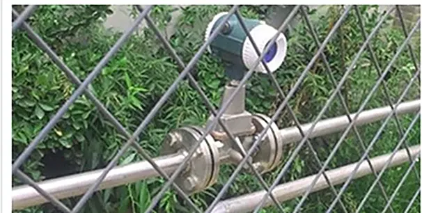
Industrial vortex flow meters take the same shedding physics and engineer away the weaknesses the automotive world discovered. Where a pod filter ruins a MAF reading, a process meter specifies a straight, undisturbed approach: typically 10 or more pipe diameters upstream, 5 downstream, and more after pumps and control valves. Our straight run guide tabulates the counts. Where the ECU needed an IAT sensor, a steam or gas vortex meter adds temperature and pressure transmitters so the flow computer outputs mass or standard volume directly.
And where the car sensor lived within a fixed airflow band, a process meter is sized so the Reynolds number stays above roughly 20,000 across the working range. You can check that in seconds with our Reynolds number calculator.
The output still begins as a frequency: each meter carries a K-factor in pulses per unit volume. The transmitter converts the count to 4-20 mA, HART, or pulse output. If that is the instrument you came for, start with the flanged vortex flow meter for lines up to DN300, the insertion vortex meter for large ducts and mains, or the sanitary vortex flow meter for food and pharmaceutical lines. The full lineup is on the vortex flow meter range page.
For saturated or superheated steam, the compensated options are collected on the steam flow meter page. For plant compressed air, a thermal mass flow meter is often the better fit at low velocities.
Application example
Logistics trading company, United Kingdom. The inquiry called for an air flow meter on a DN100 line: 150 to 1,500 m³/h, 4-20 mA output with HART, 12-24 VDC supply, IP65 housing, rated 16 bar and 200 °C. We proposed a DN100 wafer-style vortex flow meter meeting the full specification, with UK delivery terms included in the offer.
Mounting any of these meters on a vertical line brings its own set of rules; they are collected in our vertical flow meter installation guide.
FAQ
What cars have a Karman Vortex air flow sensor?
Mostly Japanese cars of the late 1980s and 1990s: the Mitsubishi Eclipse, Eagle Talon, and Plymouth Laser, plus the Mitsubishi 3000GT and Dodge Stealth. The Toyota Supra Turbo with the 7M-GTE engine, early Lexus LS400 V8s, and several Mitsubishi Pajero and Lancer Evolution models also used one. Later engines switched to hot-wire MAF sensors.
What is a Karman vortex mass air flow sensor?
It is an intake air flow sensor that counts the vortices shed behind a small obstruction; the count rate is proportional to air velocity. Because the count measures volume, the assembly includes an intake air temperature sensor and often a barometric sensor. With those inputs, the engine control unit converts the frequency into air mass.
What is the disadvantage of a Karman vortex sensor?
It is sensitive to disturbed intake flow: turbulence from an open pod filter or missing ducting causes missed vortex counts and lean running. The optical versions can be damaged by solvent cleaning, and replacement units for 1990s vehicles are scarce. The frequency output also needs temperature and pressure inputs to yield true mass flow.
How do I tell if my air flow sensor is bad?
Look for lean running, hesitation, stalling, and MAF-range codes such as P0100 to P0103. Then check the signal. At idle the sensor should output a steady square wave, around tens of Hz on most designs, that rises smoothly with engine speed. No signal with good power and ground, or an erratic frequency at steady rpm, points to the sensor or its approach ducting.
Request a quote
We supply industrial vortex flow meters for steam, gas, compressed air, and liquids, from DN15 flanged bodies to insertion probes for large mains. Tell us the application: line size, fluid, flow range, temperature, and pressure, and we will size the meter and quote with the right compensation options. Reach our application engineers or use the form below.
Written and technically reviewed by Wu Peng and the Instranova engineering team.