By Wu Peng, Senior Process Instrumentation Engineer · Last reviewed August 28, 2026
A refrigerant flow meter has a harder job than the name suggests. The same circuit carries a liquid near 1,280 kg/m³ in one pipe and a vapor near 14 kg/m³ in another. The liquid loses about 14 percent of its density between winter and summer condensing conditions, and none of the common refrigerants conducts electricity. Those facts decide where a meter can go, which technologies survive there, and why the spec is written in kg/h rather than m³/h.
This guide covers refrigerant flow measurement on real circuits: chillers, heat pumps, refrigeration racks, charging lines and compressor test stands. It starts with a naming problem: in HVAC service language a metering device is not a meter at all. A wrong search here sends people to expansion valves and refrigerator spare parts. Then it works through the mass flow arithmetic, the placement rules that phase change imposes, the technology shortlist, and the standards and regulations that make the numbers matter.
Contents
- Meter or metering device
- Mass flow from capacity
- Placement and phase
- Choosing the technology
- Test stands and standards
- Charge accounting rules
- FAQ
Meter or metering device
Three unrelated products answer to this keyword, and separating them saves procurement time. In HVACR trade language, the metering device is the expansion element. That means the TXV, electronic expansion valve, fixed orifice or capillary tube that throttles liquid refrigerant into the evaporator and holds superheat.
It regulates flow; it does not measure or report anything. If a service manual says the metering device is restricted, that is a valve problem, not an instrumentation topic.
The second is the laboratory teaching flowmeter: a small variable-area glass tube fitted to refrigeration demonstration benches, where it often doubles as the throttling element. It belongs to the classroom, not to plant metering.
The third is the appliance spare part. Domestic refrigerators carry a tiny water flow sensor for the drinking-water dispenser, sold under part numbers that share this search term. It never touches refrigerant. Everything below concerns the industrial instrument: a meter that reports refrigerant flow as a signal you can total, log and act on.
Mass flow from capacity
Refrigerant flow specifications start from thermodynamics, not from pipe size. Cooling capacity divided by the refrigeration effect gives the mass flow the circuit must move: m = Q / Δh, with Q in kW and Δh in kJ/kg across the evaporator.
Two worked numbers show the range. A 350 kW chiller on R134a has a refrigeration effect near 143 kJ/kg between a 40 °C condensing liquid and a 0 °C evaporator. It therefore moves 350 / 143 = 2.45 kg/s, about 8.8 t/h.
The same 350 kW on ammonia, whose refrigeration effect is near 1,100 kJ/kg, moves only 0.32 kg/s, about 1.15 t/h. Equal cooling, roughly an eighth of the mass flow: the meter for an ammonia circuit is sized very differently from its R134a counterpart.
Mass is also the only stable unit of record, because refrigerant density moves with operating conditions. The table anchors the numbers.
| Refrigerant | Saturated liquid density | What it means for the meter |
|---|---|---|
| R134a | About 1,280 kg/m³ at 5 °C, falling to about 1,100 kg/m³ at 50 °C | A volumetric reading drifts about 14% across the seasonal envelope with no change in mass flow |
| R410A | About 1,060 kg/m³ at 25 °C | High pressure rather than density is the sizing constraint; bodies see 30 bar and more |
| R717 ammonia | About 609 kg/m³ at 20 °C | Low density plus high refrigeration effect gives small mass flows; wetted parts must be copper-free |
| R744 CO2 | About 927 kg/m³ at 0 °C, collapsing to about 598 kg/m³ at 30 °C near the 31 °C critical point | Density becomes unusable as a conversion constant; measure mass directly |
A vapor line multiplies the problem. Saturated R134a vapor at 0 °C sits near 14.4 kg/m³, almost ninety times thinner than the liquid, so the same mass flow needs a far larger volumetric range.
This is the practical case for a Coriolis mass flow meter as the default refrigerant mass flow meter. It reports kg/h directly and carries its own density reading, so no external correction chain exists to drift. The general argument is covered in our mass versus volumetric flow guide; refrigerants are its sharpest example.
The pipe arithmetic stays ordinary once mass is settled. The 8.8 t/h of liquid R134a above is 7.3 m³/h at 1,200 kg/m³, which a DN40 line carries at about 1.6 m/s.
Placement and phase
Refrigerant flow measurement has one placement rule that outranks every technology preference: establish the phase at the meter location first. A refrigeration circuit offers only a few single-phase windows, and the meter must sit inside one of them.
The first choice is the liquid line between condenser or receiver and the expansion valve, with confirmed subcooling of at least 5 K at the meter. Subcooled liquid is dense, stable and single-phase, and every liquid technology performs at its datasheet number there. The margin matters because the meter adds a pressure drop of its own. If the liquid arrives saturated, that drop can flash part of it to vapor inside the measuring section, and the reading turns noisy in the way entrained gas always reads.
The second window is superheated vapor: the discharge line after the compressor, or the suction line when superheat is verified. Vapor metering is a gas application, with gas-range sizing and a density or mass basis to make the number meaningful. The segment that is out of bounds is the run from expansion valve outlet to evaporator: it is two-phase by design, and no meter type returns a dependable number inside it.
Keep the liquid meter at a low point or in a rising run so the section stays full, and keep it away from the receiver outlet vortex. If the line runs long and uphill, check subcooling again at the meter elevation, because static head subtracts from it. On heat pump circuits that reverse, a bidirectional meter saves a second installation.
Choosing the technology
One elimination comes before the table. Every common refrigerant, from HFC and HFO fluids to propane, CO2 and ammonia, is electrically non-conductive, and a magnetic flow meter needs conductivity above about 5 µS/cm to produce a signal. On refrigerant it reads nothing. Any type list that includes it has not been checked against the physics.
| Technology | Reads | Where it works on refrigerant | Watch for |
|---|---|---|---|
| Coriolis | Mass + density | Liquid line, charging, test stands; gas with care | Body pressure rating; skid vibration; entrained vapor reads low |
| Vortex | Volume | Superheated discharge vapor at lower cost | Needs external density compensation; low suction density can fall below range |
| Thermal mass | Gas mass | Dry vapor only, with a calibration for that refrigerant | Any liquid carryover invalidates the reading |
| Turbine | Volume | Clean single-phase liquid | Bubbles degrade accuracy quickly; low lubricity wears bearings |
| Gear / PD | Volume | Small charging and dosing streams | Low viscosity raises internal slip; verify at the real viscosity |
| Variable area | Volume, local | Sight indication on lab and bench rigs | Scale is fluid-specific; not a plant metering instrument |
Two refrigerant-specific corrections apply on top of the table. The first is oil circulation. Compressor oil travels with the refrigerant at typically 0.5 to 5 percent by mass, so a mass meter totals oil plus refrigerant together.
For most control tasks the bias is ignorable; for a charge balance or a compressor test it is not. That is why oil concentration sampling per ASHRAE 41.4 exists, and why an oil circulation rate near 5 percent is also an efficiency problem by itself.
The second is pressure rating by refrigerant. R410A circuits put more than 30 bar on the meter body, and transcritical CO2 gas coolers run in the 85 to 120 bar band. The wetted rating is therefore selected against the relief setting of that circuit, not against a catalog default. Hydrocarbon refrigerants such as propane add an intrinsically safe certification requirement, and ammonia adds the copper-free materials rule; both are covered in their own guides.
Test stands and standards
Compressor and chiller test benches are where refrigerant metering is most demanding, and also where its role is most often misunderstood. Under AHRI 550/590, chiller capacity is rated from the water side: water flow times temperature difference, with the method of test drawn from ASHRAE Standard 30. The refrigerant-side meter on an OEM stand is the development and verification instrument, cross-checking the water-side balance and catching drift between the two.
That cross-check role is why stands specify 0.1 to 0.2 percent Coriolis accuracy and small line sizes. A low flow Coriolis meter in DN3 to DN15 covers most compressor calorimetry and charging work, reading mass directly at flows where a volumetric meter would be working at the bottom of its range. Charging lines for small hydrocarbon systems push the same requirement further down, to grams-per-cycle dosing.
Application example
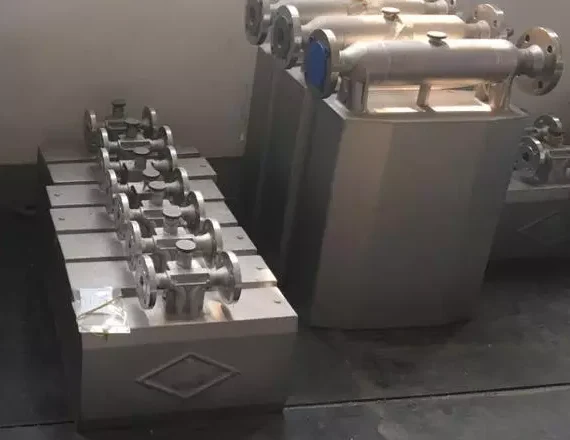
Liquid-line R134a metering. A refrigeration client in Russia asked us to meter liquid R134a at 0.5 to 1 kg/s on a 1/2 inch connection, at up to 25 bar and 60 °C. We proposed a DN15 Coriolis mass flow meter with ±0.2 percent accuracy and a 4–20 mA output, its display configured for instantaneous flow, total, density and temperature. On a liquid line that density readout also works as a continuous condition check: a value below the expected liquid density flags vapor in the line.
Charge accounting rules
An increasing share of refrigerant metering exists for regulators rather than for process control. In the United States, EPA rules for appliances holding 50 pounds or more of regulated refrigerant set annualized leak-rate triggers. The thresholds are 30 percent for industrial process refrigeration, 20 percent for commercial refrigeration and 10 percent for comfort cooling, and crossing one forces repair, verification and record-keeping. A metered charge and recovery record is the clean way to know the rate before an auditor computes it for you.
In the EU, F-Gas rules scale leak checking with the charge expressed in CO2-equivalent tonnes: from 5 t CO2e a yearly check, from 50 t twice yearly, from 500 t quarterly, with intervals halved in reverse where fixed leak detection is installed. The higher the GWP of the fluid, the smaller the charge that crosses each line, which pushes plants toward measured charge logs.
Flammable refrigerants regulate the other end of the scale. The 2019 edition of IEC 60335-2-89 raised the charge limit for A3 fluids such as R290 in self-contained commercial appliances from 150 g to 500 g, and to 1,200 g for A2L fluids. Appliance lines that dose to those limits meter each charge to gram accuracy, which is gear meter and micro Coriolis work rather than plant metering.
The energy side of the same circuits is a separate measurement. Cooling delivered to the building loop is metered on the water side, and that method lives in our BTU metering guide.
FAQ
How can I measure the flow rate of refrigerant?
Two routes exist. The direct route is a flow meter in a single-phase section of the circuit, ideally a Coriolis mass flow meter in the subcooled liquid line, which reports kg/h without any density correction. The indirect route calculates mass flow from measured cooling capacity: m = Q / Δh, so a 350 kW R134a chiller with a 143 kJ/kg refrigeration effect moves about 2.45 kg/s. Plants use the second method for checks and the first wherever the number must stand on its own.
What is a flow meter in HVAC?
The term covers two different things. An HVAC flow meter in the instrumentation sense measures water or refrigerant flow and outputs a signal. When HVAC technicians say metering device, they mean the expansion element instead: the TXV, piston or capillary tube that throttles refrigerant into the evaporator, which controls flow and measures nothing. Diagnosing a restricted metering device is valve work; measuring refrigerant flow is the subject of this guide.
How does a refrigerant mass flow meter work?
A refrigerant mass flow meter is almost always a Coriolis instrument. The refrigerant passes through one or two vibrating tubes, and the flowing mass twists the vibration by a small phase shift that is directly proportional to mass flow in kg/h. The same tube’s resonant frequency reports fluid density, so the transmitter outputs mass flow, density and temperature together, unaffected by the pressure and subcooling swings that shift refrigerant density.
Request a quote
Tell us the refrigerant, the line section and pipe size, the flow range in kg/h, the working and relief pressures, and any certification the site requires. We will propose a metering configuration sized for the real phase conditions at the installation point. Reach our application engineers or use the form below.
Written and technically reviewed by Wu Peng and the Instranova engineering team.