By Wu Peng, Senior Process Instrumentation Engineer · Last reviewed August 3, 2026
A BTU meter measures the thermal energy a chilled water or hot water loop delivers, not just the flow through it. It combines three parts: a flow meter, a matched pair of temperature sensors on the supply and return lines, and an energy calculator. The calculator multiplies flow by temperature difference and integrates the result over time. The same instrument is sold as a thermal energy meter, an energy meter, or a heat meter.
BTU stands for British thermal unit: the heat that raises one pound of water by one degree Fahrenheit.
On a typical chilled water loop running 44 °F supply and 54 °F return, the temperature measurement, not the flow measurement, sets most of the billing uncertainty. A ±0.15 °F sensor pair on a 10 °F delta-T already contributes 1.5 percent of energy error before the flow meter adds anything. This guide works through the energy equation with real numbers, compares the flow meter options, and covers sensor pairing, glycol, installation, and the certifications that matter for billing.
Contents
- BTU meter basics
- Working principle
- The energy equation
- Flow meter options
- Temperature sensor pairs
- Glycol correction
- Installation guidelines
- Outputs and certifications
- Selecting a BTU meter
- FAQ
BTU meter basics
A flow meter alone tells you how many gallons moved. A BTU meter tells you how much cooling or heating those gallons carried, which is what an energy bill or a chiller plant efficiency number actually needs. That is the whole difference between a BTU meter and a flow meter: the added temperature pair and the calculator turn a volume total into an energy total.
The typical applications are chilled water and hot water in commercial buildings, district cooling and district heating networks, and campus loops where each building pays its share. Process cooling circuits use the same meters when a utility manager wants cost per department. HVAC meters usually read in ton-hours or kBtu; district energy plants bill in kWh or GJ. The Middle East district cooling market is a large part of global demand for these meters.
Working principle
Every BTU meter has the same three parts. First, a flow sensor in one leg of the loop reports volumetric flow. Second, a matched pair of RTD temperature sensors reads the supply and return lines at the same moment. Third, an energy calculator samples both inputs every few seconds, computes instantaneous thermal power, and integrates it into a cumulative energy total, the billing register.
The calculator also stores the fluid properties. Density and specific heat change with temperature, and they change a lot with glycol concentration. A billing-grade calculator therefore evaluates them at the measured temperature instead of using one fixed constant. That detail decides whether the meter stays accurate across seasons.
The energy equation
In US units the working formula is short:
Q (Btu/h) = GPM × 500 × ΔT (°F)
The 500 is not arbitrary. Water weighs about 8.33 pounds per gallon near 60 °F, there are 60 minutes in an hour, and water absorbs 1 Btu per pound per degree Fahrenheit. Multiply the three and you get 8.33 × 60 × 1, which is roughly 500.
At chilled water temperatures the density is slightly higher. The shift moves the constant by less than half a percent, so 500 serves for both heating and cooling water.
Glycol mixtures are a different story, covered below.
Worked example on a real riser: 300 GPM of chilled water at 44 °F supply and 54 °F return gives ΔT = 10 °F.
Q = 300 × 500 × 10 = 1,500,000 Btu/h, which is 1,500,000 / 12,000 = 125 tons of refrigeration.
Held for one hour, that load consumes 1.5 MMBtu, which is 125 ton-hours, or 1,500,000 / 3,412 = 439.6 kWh of thermal energy. Keep power and energy separate when you check a meter: Btu/h and tons describe the instantaneous rate, while Btu, ton-hours, and kWh describe the accumulated total. Several published worked examples multiply a tonnage figure by 3.517 and label the result kWh. That converts to kW, a power; it only becomes kWh after multiplying by the hours.
If your commissioning math mixes the two, the meter will look broken when it is fine. Unit conversions for the flow side are collected in our flow rate units guide.
| Unit | Equivalent |
|---|---|
| 1 ton of refrigeration | 12,000 Btu/h (a rate of cooling) |
| 1 ton-hour | 12,000 Btu (energy) |
| 1 kWh | 3,412 Btu |
| 1 MMBtu | 1,000,000 Btu, about 1.055 GJ or 293.1 kWh |
Rounded working values; 1 kWh = 3,412.14 Btu exactly.
Flow meter options
Two flow technologies carry almost all chilled water energy metering: transit-time ultrasonic and electromagnetic. Both put zero obstruction in the pipe and zero pressure drop on the pumps, which matters on loops that run nearly year-round.
| Criterion | Ultrasonic (transit-time) | Electromagnetic |
|---|---|---|
| Typical accuracy | ±1% of reading inline; ±1–2% clamp-on | ±0.5% of reading; ±0.2% optional |
| Straight run | 10D upstream, 5D downstream | 5D upstream, 2–3D downstream |
| Fluid requirement | Clean, acoustically uniform liquid | Conductivity above 5 µS/cm |
| Retrofit without shutdown | Yes, with clamp-on transducers | No, flanged or wafer body |
| Pressure drop | None | None |
Representative manufacturer specifications; confirm per datasheet for a given size and velocity range.
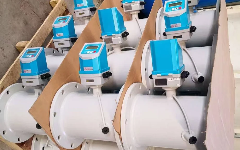
The practical split: on an occupied building where the riser cannot be drained, a clamp-on ultrasonic flow meter goes on in an afternoon with no pipe work. On new construction the meter can be specified into the pipe spec. There, an inline ultrasonic flow meter with a factory-aligned acoustic path or a magnetic flow meter gives the tighter accuracy that billing prefers.
On large distribution mains an insertion ultrasonic flow meter keeps the installed cost reasonable above DN300. All of these appear in our ultrasonic flow meter range.
Temperature sensor pairs
The temperature sensors are sold as a matched pair for one reason: the energy reading depends on the difference between two measurements, not on either absolute value. Two individually decent sensors that each read within ±0.5 °F could disagree by a full degree. A factory-matched pair tracks each other to a small fraction of that. Good billing pairs are matched to better than ±0.15 °F across the working range.
Divide the pair error by the delta-T and you get the energy error it causes. The percentage grows fast as delta-T falls:
| Loop ΔT | Energy error from a ±0.15 °F pair |
|---|---|
| 12 °F | ±1.25% |
| 10 °F | ±1.5% |
| 6 °F | ±2.5% |
| 4 °F | ±3.75% |
| 2 °F | ±7.5% |
Error relative to true energy, temperature contribution only; the flow meter error adds on top.
This is why low delta-T syndrome is a metering problem as well as a chiller problem. A plant designed for 10 to 16 °F may actually run at 4 °F. That alone more than doubles the temperature share of the metering error, without anyone touching the meter. EN 1434, the international heat meter standard, builds the same physics into its limits.
The permitted error of the sensor pair is ±(0.5 + 3 × ΔTmin/ΔT) percent. For a pair rated down to 3 K, that works out to ±1.4 percent at a 10 K delta-T.
Wiring matters as much as matching. Two-wire pairs only stay matched if both lead runs have identical resistance, which is why factory-paired sensors ship with equal cable lengths that should not be trimmed. Three-wire and four-wire connections cancel the lead resistance instead; our 3-wire RTD guide covers the arithmetic, and the sensors themselves are standard Pt100 or Pt1000 RTDs. For billing, mount both sensors in insertion thermowells; surface-mounted strap-on sensors respond slowly and read the pipe wall, which is acceptable for trending but not for revenue.
Glycol correction
Chilled water loops with outdoor piping or low-temperature process service often run propylene glycol, and glycol changes both density and specific heat. A 30 percent propylene glycol mix around 40 °F carries about 6 percent less heat per gallon per degree than plain water. Its effective constant is roughly 471 instead of 500.
A calculator left on the water setting over-reads the delivered energy by about 6 percent on that mix. The deviation grows as the fluid gets colder and richer.
The fix is configuration, not a new meter. Billing-grade calculators take a glycol type and concentration setting, or a programmable heat coefficient. Enter the concentration from a refractometer check, not from the design drawing. Loops get topped up with plain water over the years and drift away from the specified mix.
Why volumetric metering needs fluid properties at all is covered in our guide to mass flow versus volumetric flow.
Installation guidelines
The question that comes up on every project is whether the flow meter belongs in the supply or the return. The practical answer: either line can work, and the choice matters less than the configuration. On chilled water the return runs warmer, so a meter there collects less condensation on its electronics and transducers; that is the common preference. What is not optional is telling the calculator which side the flow sensor sits on, because it evaluates density and specific heat at that line’s temperature.
A meter programmed for the wrong side carries a small systematic error forever.
The rest of the checklist is familiar pipe practice. Give the flow sensor its straight run: 10D upstream and 5D downstream for ultrasonic, 5D and 2 to 3D for electromagnetic. Allow more after a pump or a throttling valve. Keep the pipe full; meter in a riser or a low horizontal run, never at a high point that can trap air.
Ground an electromagnetic meter to the pipe on both sides. Route the RTD and flow signal cables away from VFD output cables, in their own conduit. On cold lines, re-insulate over the meter body with a vapor barrier but leave the transducer and the connection head reachable; a buried meter never gets its periodic verification. Set the calculator’s low delta-T cutoff so night circulation with the coils closed does not register phantom energy.
Outputs and certifications
Most of a BTU meter’s value flows through its data connection. BACnet MS/TP is the default in North American commercial buildings; the meter shows up as a device with objects for power, flow, both temperatures, and totalized energy. Modbus RTU covers plant SCADA and most Asian and European process installations. M-Bus, per EN 13757, dominates European tenant billing because it is two-wire and bus-powered.
A bare pulse output remains useful as a check channel against a portable reference.
Certification is where chilled water metering gets specific. EN 1434 is the governing standard for heat meters in Europe and much of the Gulf: it defines accuracy Class 1, 2, and 3 with formulas rather than flat percentages. A Class 2 flow sensor, for example, is allowed ±(2 + 0.02 qp/q) percent, and the calculator ±(0.5 + ΔTmin/ΔT) percent. In the United States, ASTM E3137 is the heat meter specification; Canada requires Measurement Canada approval for meters used in billing.
Note that despite what some older articles claim, there is no AHRI certification program for BTU meters; specifications citing one cannot be met by any vendor. For billing service, plan on periodic verification of the installed meter; Germany, for instance, requires re-verification every six years. Plant-efficiency meters are commonly checked annually against a portable clamp-on reference meter; our flow meter calibration guide walks through that check.
Selecting a BTU meter
Work the decision in this order. First, retrofit or new build: an occupied building points to clamp-on ultrasonic, new pipe points to inline ultrasonic or electromagnetic. Second, the purpose: tenant billing needs a certified meter class, matched thermowell-mounted sensors, and a verification plan; plant efficiency monitoring can accept clamp-on sensors and looser class. Third, pipe size: full-bore meters get expensive above DN300, where insertion types take over.
Fourth, the fluid: confirm glycol type and concentration before the calculator is ordered. Portable instruments have a place too; a handheld transit-time set is how you survey a plant before committing to permanent metering points. US distributor listings start under 1,000 dollars for a small impeller meter with an energy monitor. Large certified billing sets run past 14,000 dollars.
Application example
Trading house, United Arab Emirates. The customer requested clamp-on ultrasonic flow meters together with pressure and temperature transmitters for process lines, delivered as one package to a free-zone warehouse. The inquiry shows the pattern behind most metering points: the flow meter is only one of the instruments, and everything around it has to match its process connections and signal levels. We proposed the clamp-on sets and the transmitters as one configured package rather than as separate line items.
Instranova supplies the full metering point from stock configurations. TUF-2000-series converters accept a paired Pt100 input for thermal energy, with clamp-on, inline, and insertion transducer sets; electromagnetic meters cover plant rooms with short straight runs. Quote checklist, five points: pipe size and material; design flow and delta-T; fluid, with glycol type and percentage; mounting line and available straight run; output protocol and any certification requirement. Tell us the application and we configure one system, not a shelf part.
The same paired flow and temperature arrangement is used to value returned steam condensate, where the energy per kilogram and the flash losses are set out in the guide on condensate flow meters.
FAQ
What is the BTU meter?
A BTU meter is an instrument that measures thermal energy delivered by a liquid loop. It multiplies measured flow by the temperature difference between supply and return, then totals the result over time in Btu, ton-hours, or kWh. It is also called a thermal energy meter or heat meter.
What is a BTU meter for AC?
In air conditioning, a BTU meter sits on the chilled water serving a building, floor, or tenant and records how much cooling energy was consumed. Property managers use the totals to bill tenants their actual share of the central plant instead of allocating by floor area.
What are the disadvantages of using a BTU meter?
Cost and sensitivity to low delta-T. A certified meter with matched sensors and thermowells costs far more than a bare flow meter. When the loop runs a small temperature difference, a fixed sensor pair error becomes a large percentage of the energy reading. Glycol mixes also need explicit configuration or the totals drift high.
What is a BTU meter for gas?
Different device. On natural gas, “BTU” usually refers to the energy content of the gas. That is measured by a gas meter plus a heating-value figure from the utility, or rated as the capacity of a residential meter. The hydronic BTU meters in this guide measure liquid heating and cooling loops.
Request a quote
Send us the five checklist points above. We will return a configured BTU metering proposal, with the flow meter, matched temperature pair, and calculator specified as one system. Reach our application engineers or use the form below.
Written and technically reviewed by Wu Peng and the Instranova engineering team.