By Wu Peng, Senior Process Instrumentation Engineer · Last reviewed August 10, 2026
Flow meter troubleshooting works best in a fixed order: confirm the process actually changed, then check the installation, then the wiring and signal, and only then suspect the meter itself. Many reported meter failures land in the first three groups, and the symptom pattern tells you which one before any tool comes out.
This guide covers the six symptoms that account for nearly every service call: no reading, a reading stuck at zero with real flow, a reading with no flow, steady high or low readings, unstable readings, and a negative or reversed reading. It maps each to causes and field checks across magnetic, vortex, turbine, ultrasonic, Coriolis, and differential pressure meters, with the straight-run and signal numbers to judge each check.
Contents
- Rule out the process
- Symptom to cause
- Offset or erratic
- Straight run check
- Air and empty pipe
- Electrical checks
- Wrong technology
- FAQ
Rule out the process
A flow meter that reads oddly is often reporting the process, not failing. Before condemning the instrument, ask what else agrees with it. Pump amps, valve positions, tank level trends, and downstream pressure all carry flow information; if the level in the receiving tank is rising more slowly, the low reading on the meter is probably true.
A meter that disagrees with every other signal in the loop justifies the service call. A meter that agrees with them is reporting a process change.
The same discipline applies to comparisons over time. A reading that stepped on the same day a pump was swapped, a strainer was cleaned, or a control valve was rebuilt points at the change, not the meter. Keep to the sequence of process, installation, signal, then meter, and most visits get shorter.
Symptom to cause
Six symptoms cover nearly everything. The table pairs each with the likely causes and a check you can run in the field without pulling the meter.
| Symptom | Likely causes | Field check |
|---|---|---|
| No reading, dead display | Supply, fuse, wiring, failed converter | Verify supply voltage at the meter terminals, then the fuse |
| Zero reading, real flow | Closed valve, flow below the low-flow cutoff, stuck rotor, empty-pipe alarm active | Confirm valve lineup; compare flow against the meter minimum |
| Reading with no flow | Pipe vibration (vortex), grounding or empty pipe (magnetic), zero drift (Coriolis) | Block the line full and watch the zero for several minutes |
| Reads steadily high or low | Installation effects, wrong K-factor or range, deposits, worn bearings | Compare against a reference meter or tank draw-down |
| Unstable reading | Entrained gas, pulsating flow, electrical noise, half-full pipe | Check AC ripple on the signal; listen for pump pulsation |
| Negative or reversed | Meter installed against the flow arrow, swapped signal wires | Check the body arrow against actual flow direction |
A zero reading at low flow is often designed behavior: vortex meters force the output to zero below the low-flow cutoff, and turbine meters stop registering below their minimum flow.
Offset or erratic
When the meter reads but reads wrong, the shape of the error is the diagnosis. A steady offset that scales with flow points at calibration or installation: a distorted velocity profile from a nearby elbow, a worn turbine bearing, or a K-factor that no longer matches the meter. An erratic reading that jumps around points at the fluid or the signal: bubbles, pulsation, or electrical interference. The two groups have different fixes, so sort the symptom first.
Steady offsets respond to arithmetic. If a proving run or a reference comparison shows the meter reading 0.50 percent high, the correction is a K-factor update from 1000 to 1005 pulses per liter, not a guess at the display. The procedure, and when a field comparison is enough versus a lab calibration, is covered in our flow meter calibration guide. Field verification against a reference is good practice; adjusting the meter should wait for a documented, repeated error.
Direction carries information too. A part-open butterfly valve or a double elbow close upstream distorts the velocity profile enough to push some meter types tens of percent off, and the error direction depends on the technology and the disturbance. If the reading stepped after piping work, walk the line before touching the meter.
Straight run check
Upstream disturbances are the most common cause of a meter that reads steadily wrong. Each technology needs a different settling length, quoted in pipe diameters (D) upstream / downstream:
| Meter type | Typical straight run |
|---|---|
| Magnetic | 5D / 3D (10D after heavy swirl) |
| Vortex | 40D / 20D for a fully developed profile; some designs accept 10D / 5D |
| Turbine | 10D / 5D, with an upstream strainer |
| Clamp-on ultrasonic | 10D / 5D, up to 30D downstream of pumps |
| Thermal mass | Long: on the order of 28D after one elbow, more after stacked fittings |
| Coriolis | None required |
| Oval gear / PD | None required; fit an upstream strainer |
Always defer to the meter manual; requirements grow after double elbows in different planes. Details in our straight run requirements guide.
Flow conditioners can shorten these lengths, but they are technology specific: conditioning plates work well ahead of thermal mass meters, while vortex meter manufacturers advise against plates ahead of the shedding element, and at least one magnetic meter manufacturer reports that a straightener close upstream makes the disturbance worse. Check the manual for the meter you have rather than assuming a conditioner is always an upgrade.
Air and empty pipe
Entrained gas and part-full pipes produce different signatures on different meters, which makes them useful for diagnosis. A magnetic meter with fine bubbles reads high, because gas displaces conductive liquid while the velocity signal survives; a fully empty pipe should trip the empty-pipe detection and drive the reading to zero. A turbine meter over-speeds on gas slugs. A transit-time ultrasonic meter loses signal strength and eventually drops out.
A Coriolis meter responds to entrained gas with rising drive gain in its diagnostics, which makes drive gain the first thing to check on any suspect Coriolis reading.
One correction worth making: a magnetic meter that shows a reading on an empty line does not need a zero calibration. The reading means the empty-pipe detection is off, misconfigured, or defeated by conductive coating on the electrodes. Zeroing the meter in that state hides the symptom and corrupts the calibration. Enable and configure the empty-pipe function, or fix the piping so the tube stays full; a rising section downstream keeps a horizontal meter flooded.
Vibration does something similar to vortex meters: pipe vibration near the shedding frequency can generate a reading with no flow at all. The check is cheap: block in the line so it is full and still, and watch the output. If it reads flow, work through mounting, supports, and the low-flow cutoff setting before suspecting electronics. The mechanics are covered on our vortex flow meter page.
Electrical checks
Electrical faults imitate process faults, so a few terminal checks pay for themselves. On magnetic flow meters the signal at the electrodes is tiny, a fraction of a millivolt to a few millivolts at normal velocities, which is why grounding dominates the fault list. Confirm the grounding rings or electrode straps are connected, the shield is grounded at one end, and the meter shares a ground with the fluid.
Coil resistance against the manual value and electrode circuit continuity separate a damaged sensor from a converter problem; conductivity below the meter minimum, about 5 µS/cm for common designs, produces an unstable reading no wiring will fix.
On turbine meters, the pickup coil check takes one minute: read the coil resistance against the datasheet, then pass a small steel tool quickly under the pickup and watch for output pulses. Pulses with the tool but not with flow mean the rotor, not the electronics: debris, a seized bearing, or a missing blade. No pulses at all mean the coil or preamplifier.
The 4-20 mA side of any flow meter fails the same way a pressure loop does: current bands, supply voltage budget, and sense resistor checks are identical, and our pressure transmitter troubleshooting guide covers those tests in detail. For pulse outputs, remember the totalizer: if the display shows rate but the total never moves, the fault sits in the pulse path or the counter configuration, a distinction our flow totalizer guide unpacks.
Wrong technology
Some meters cannot be fixed because nothing is broken: the technology does not match the application. A vortex meter asked to read below its low-flow cutoff will output a clean zero forever. A magnetic meter on demineralized water has no conductive fluid to measure.
A turbine meter on a dirty stream wears out its bearings quickly. A clamp-on ultrasonic meter on a heavily scaled pipe never gets a stable signal. In each case the troubleshooting ends with a selection decision, not a repair.
Application example
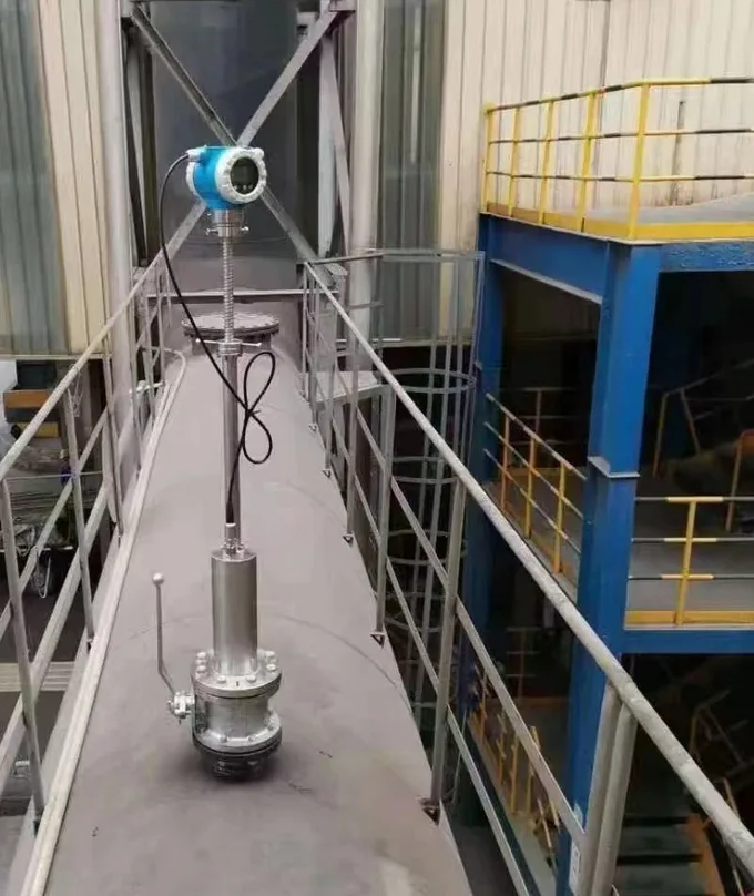
Manufacturing plant, Sri Lanka. A compressed air line needed reliable flow measurement, and a vortex meter could not meet the conditions on the line, where air temperature runs up to about 40°C. Rather than force the technology, we proposed a DN65 thermal mass flow meter for the line, a technology better matched to compressed air measurement.
If the diagnosis points the same way, compare technologies rather than replacing like with like. Our flow meter types guide maps each technology to the services it handles, and the flow meter range covers magnetic, turbine, Coriolis, thermal mass, and clamp-on ultrasonic meters for the swap.
Half of these checks depend on knowing which end of the line you are standing at, which is what upstream and downstream in piping covers.
FAQ
What are common problems with flow meters?
The recurring ones are installation effects from short straight runs, entrained gas or part-full pipes, grounding and electrical noise, deposits on electrodes or rotors, readings below the low-flow cutoff, and calibration drift. Outright electronics failures are less common; many service calls end at the installation or the process rather than inside the meter.
Why is my flow meter not working properly?
Match the symptom first. A dead display is power or wiring; a zero reading with real flow is a valve, a stuck rotor, or flow below the meter minimum; a reading with no flow is vibration, grounding, or empty-pipe detection. A steady error is installation or calibration, and an unstable reading is gas, pulsation, or electrical noise.
What is the acceptable error for a flow meter?
It depends on the technology and the job. Coriolis meters run around 0.1 to 0.2 percent of reading, magnetic and turbine meters around 0.5 percent, vortex and clamp-on ultrasonic around 1 percent. Custody transfer points need the tight end; a cooling water balance can live with several percent. Judge a meter against its own class, not against zero.
How do I calibrate a flow meter?
Verify in the field, calibrate against a reference. Field checks compare the meter with a reference meter, a tank draw-down, or a clamp-on comparison; lab calibration runs the meter against a gravimetric or master-meter rig and issues a certificate. Adjust only on a documented, repeated error, and record as-found and as-left values every time.
Request a quote
If troubleshooting points to a meter that does not fit the service, tell us the fluid, line size, flow range, and temperature, and we will propose a technology that matches the application. Reach our application engineers or use the form below.
Written and technically reviewed by Wu Peng and the Instranova engineering team.