By Wu Peng, Senior Process Instrumentation Engineer · Last reviewed October 14, 2026
Bubbler level measurement pushes a small, steady flow of air or nitrogen down a dip tube that ends near the bottom of the tank. To leave the tip, the gas has to overcome the liquid head, so the back pressure in the line equals that head. A pressure transmitter at the top converts it to level: h = P / (SG × ρw × g). SG is the liquid’s specific gravity and ρw the density of water.
Only the tube touches the liquid; the transmitter sees dry gas. That is why bubbler systems still run in sumps, lime slurry tanks, acid tanks and foaming basins where a wetted sensor clogs or corrodes. The error sources are less obvious: friction in the purge line, a supply set too low, gas pushed into a closed vapor space, and density that moves with temperature. Below are the numbers for each one.
Contents
- Working principle
- Worked calculation
- Purge flow and friction
- Supply pressure
- Closed tanks
- Density with two tubes
- Pros and limits
- Troubleshooting
- Choosing the instruments
- FAQ
Working principle
A bubbler system has five parts: a clean, dry gas supply, a pressure regulator, a flow restriction with a purge rotameter, a tee to a pressure transmitter (or a gauge, for a local level indicator), and the dip tube itself. Gas flows down the tube until the pressure at the tip just exceeds the hydrostatic pressure of the liquid above it. From then on, bubbles leave the tip at a slow, steady rate and the line pressure stops rising.
The transmitter reads that line pressure: if the liquid rises, the head at the tip rises and the line pressure follows. If the level falls, the line bleeds down through the tip until it matches the new head. The flow is small, so the line acts like a gas-filled impulse line that ends at the tip. The reading is head above the tip, not above the floor.
Open-tank bubbler. The transmitter measures the gas pressure on the tee, which equals the liquid head above the tip once bubbles are leaving it.
Worked calculation
Size the transmitter to the head between the tip and the highest level, multiplied by the specific gravity. A standard level transmitter range is set in pressure units, so get the conversion right before setting the lower and upper range values (LRV and URV).
P (kPa) = (L − t) × SG × 9.80665 | P (psi) = (L − t, in inches) × SG × 0.0361
Take an open tank with a 3.0 m maximum level, a dip tube tip 0.10 m above the floor, and a liquid with SG 1.05.
| Step | Result |
|---|---|
| Head above tip at max level | (3.0 − 0.10) × 1.05 = 3.045 m H2O |
| URV in kPa | 3.045 × 9.80665 = 29.86 kPa |
| URV in US units | 119.9 inH2O = 4.33 psi |
| LRV | 0 kPa = level at the tip (0.10 m) |
| Output at 1.80 m level | (1.80 − 0.10) × 1.05 × 9.80665 = 17.50 kPa; 4 + 16 × 17.50 / 29.86 = 13.38 mA |
Add the 0.10 m tip offset back in the control system if the operators want level above the floor. Check any other pair of values with the hydrostatic pressure calculator.
The transmitter cannot see below the tip. When the level drops under 0.10 m, gas flows freely, the line falls to atmospheric pressure, and the output sits at 4 mA. Set the tip at the lowest level you need to measure, and keep it clear of settled solids.
The reading also depends on density. Water has a density of 983.2 kg/m³ at 60 °C against 998.2 kg/m³ at 20 °C, so a bubbler calibrated cold reads about 1.5% low on hot water at the same true level. On services where SG drifts, either compensate in the control system or measure density with a second tube, as shown further down.
Purge flow and friction
Keep the purge flow low and steady, typically quoted in SCFH (standard cubic feet per hour). Yokogawa’s application note states that the flow “must be low and uninterrupted,” and that its standard 2 SCFH purge rotameter range suits most applications. ControlAir’s L100 manual advises cutting the flow to about 1.5 SCFH, as long as readings stay accurate. In metric terms, 1 SCFH is 28.3 L/h, so 1 to 2 SCFH is roughly 28 to 57 L/h.
Too little flow makes the line slow to follow a rising level, because the gas must fill the extra volume first. With too much flow, friction in the tubing adds pressure that the transmitter reads as level. ControlAir gives a working formula for that offset:
PD (inH2O) = K × A × L / 1000
Here A is the flow in SCFH, L is the tubing length in feet, and K is a coefficient that depends on the tubing bore. For a 60 ft run on the 119.9 inH2O span from the example above, the result depends mostly on the tubing bore:
| Tubing (ControlAir K) | 1.5 SCFH | 3.0 SCFH |
|---|---|---|
| 1/8 in ID (70.0) | 6.3 inH2O, 5.3% of span | 12.6 inH2O, 10.5% |
| 3/16 in ID (12.5) | 1.13 inH2O, 0.94% | 2.25 inH2O, 1.9% |
| 1/4 in ID (4.0) | 0.36 inH2O, 0.30% | 0.72 inH2O, 0.60% |
| 1/4 in pipe, 0.364 in ID (0.9) | 0.08 inH2O, 0.07% | 0.16 inH2O, 0.14% |
K values from the ControlAir L100 instruction manual, Table 1. Percent of span is the offset divided by 119.9 inH2O.
Small-bore tubing on a long run turns the purge rate into a level error, and that error moves every time someone touches the needle valve. If the run has to be long, use a larger bore or a separate sensing tube from the transmitter to the dip tube, so no purge gas flows in the line being measured.
ControlAir lists the same remedies (less purge, larger tubing or a separate sense line) and notes that the separate line sees zero pressure drop because the transmitter consumes no air.
For comparison, Campbell Scientific programs its B10 hydrology bubbler for 30 to 120 bubbles per minute from a 0.25 in ID outlet, 60 by default. That range applies to that instrument; on a process dip tube, set the flow on the rotameter and check it against the friction table. On a nitrogen purge, also budget the gas: 1.5 SCFH runs about 1,080 standard cubic feet (30.6 m³) a month.
Supply pressure
The regulator must sit above the highest head the tip will ever see, or the gas stops flowing at high level and the reading flattens. Vendors state the margin differently, so name the rule you use:
| Source and rule | Applied to the 4.33 psi example |
|---|---|
| ControlAir L100: 150% of full-scale head | 6.5 psi (44.8 kPa) |
| Yokogawa: about 10 psi above max line pressure | 14.3 psi (98.8 kPa) |
Each rule applies to that vendor’s own system. On an open tank, line pressure at the tip equals the head.
The wider margin keeps the purge steadier when the plant air header sags. Put the regulator downstream of the filter and dryer, so the setting holds. If the supply is lost, Yokogawa notes that the back pressure can drop below the head and process liquid can flow back up the tube toward the rotameter and transmitter. A low-flow alarm on the purge rotameter flags that case before liquid reaches the instruments.
Check one more number against the transmitter. If the tip plugs, the line climbs to the regulator setting, so the transmitter overload rating must exceed it. For the example, a 0-30 kPa transmitter with a 1.5× overload rating tolerates 45 kPa: enough for the 44.8 kPa (150%) setting, not for 98.8 kPa. With the wider margin, choose a transmitter whose overload rating clears the regulator setting.
Closed tanks
On a sealed or pressurized vessel, the single-tube bubbler reads the liquid head plus the vapor-space pressure, and the purge gas itself adds to that vapor space. The fix is the same as for any hydrostatic measurement: subtract the top pressure. Use a differential pressure transmitter with the high side on the bubbler line and the low side on a nozzle in the vapor space.
A closed tank needs two more checks. The vent or pressure control must remove the purge gas, or tank pressure creeps up over weeks. The supply margin must also clear the head plus the maximum tank pressure; Yokogawa’s line-pressure rule covers that. If the vapor condenses in the low-side line, the reference stops being a gas leg; treat it as a wet leg or purge that line too.
Density with two tubes
Two dip tubes with tips at a fixed vertical spacing give density directly, as long as the level stays above the upper tip. The level cancels out, and the pressure difference between the two lines depends only on spacing and density.
SG = ΔP / (ΔH × 9.80665), with ΔP in kPa and ΔH in m
With tips 0.500 m apart and a differential of 5.394 kPa, SG = 5.394 / (0.500 × 9.80665) = 1.100. Feed that SG into the level calculation from the lower tube and the level reading follows density changes instead of drifting with them. The same pair of tubes can track an interface between two liquids, provided the interface stays between the tips. A DP density meter uses the same arithmetic, with two flush diaphragm seals in place of the purge tubes.
A DP transmitter across the two lines is the cleaner way to measure ΔP. Both lines carry the same purge flow, so most of their friction offsets cancel when the tubing runs match.
Pros and limits
The big advantage is that nothing electronic touches the process. The dip tube can be a plain pipe in PVDF, PTFE-lined steel or alloy. That lets a bubbler work on corrosive, abrasive, viscous and solids-laden liquids, and on foam that blinds an ultrasonic sensor. The transmitter can sit at grade or in a panel, far from heat and spray.
| Works well | Look elsewhere |
|---|---|
| Open sumps, wet wells, lime and slurry tanks | Sealed vessels where purge gas is not allowed |
| Acids and caustics that attack wetted sensors | Liquids that react with air (use nitrogen or another method) |
| Foaming or turbulent surfaces | Services with no reliable gas supply |
| Hot liquids, with the transmitter kept remote | Large density swings without a second tube |
A bubbler consumes gas continuously, needs someone to watch the rotameter, and can plug when crystals or sludge build at the tip. Compared with a submersible pressure transducer, it trades a wetted sensor for a gas supply and a small maintenance routine.
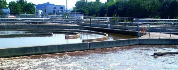
Application note
Typical bubbler services. Bubbler-style level suits open wet wells, lime slurry and sludge tanks, and acid storage, where a wetted sensor is exposed to fouling or corrosion. Before quoting, check three things: span from the tip-to-overflow head and SG, a purge rotameter covering the 1.5 to 2 SCFH that ControlAir and Yokogawa cite, and tubing bore against run length.
Troubleshooting
Most bubbler faults trace back to the gas path, so start at the rotameter and work down the tube.
| Symptom | Likely cause and check |
|---|---|
| Reads high, flat at max | Tip plugged or partly plugged; the rotameter shows low or no flow. Blow down the tube, then inspect the tip. |
| Reads high by a fixed amount | Purge set too high on small tubing. Recompute PD with the K table and reduce the flow. |
| Reads low or drifts down | Leak at a fitting or a split tube; the rotameter shows normal flow. Leak-test the joints with soap solution. |
| Stuck at 4 mA | Level below the tip, or the line open to atmosphere at the tee. Check the tip depth and the tee fittings first. |
| Noisy output | Large bubbles or a loose tube in agitation. Support the tube and cut a small notch at the tip, as ControlAir recommends, so gas leaves in a steady stream; add damping. |
| Slow to follow filling | Purge too low for the line volume. Raise the flow a little and recheck the friction offset. |
For a quick zero check, close the purge, vent the transmitter side to atmosphere, and confirm 4 mA. Then restore the purge and compare the reading with a manual dip-tape level. The pressure transmitter calibration steps apply to the transmitter itself.
Choosing the instruments
These items in our range match a bubbler:
| Item | Fit for a bubbler |
|---|---|
| SI-303 low pressure transducer | Dry gas and air service, spans 0-2.5 to 0-30 kPa (10 to 120 inWG), overload 1.5× range, 4-20 mA. Covers heads up to about 3 m of water, like the example above. |
| Gauge pressure transmitters | Deeper tanks and higher heads; ±0.075% or ±0.1% of calibrated span, 4-20 mA with HART. |
| Differential pressure transmitters | Closed tanks and two-tube density, spans from 1 kPa. |
| Low flow rotameter | Purge indicator; air from 3.5 l/h by size, optional 4-20 mA and limit alarms for a loss-of-purge alarm. |
Values from the product datasheets; confirm the range code and connection when ordering.
If the liquid allows a wetted sensor and there is no gas on site, compare the other options in our level instruments range. Bubblers also show up as one of the options in river water level measurement and molten salt level measurement. On closed, high-pressure vessels where purge gas is unwelcome, a caged displacer level transmitter is the older mechanical alternative.
FAQ
How does a bubbler level measurement work?
A regulated gas flows slowly down a dip tube until it bubbles out of the tip. The line pressure then equals the liquid head above the tip, and a pressure transmitter converts it to level with h = P / (SG × ρw × g). Only the tube is wetted.
What is a big advantage of the bubbler system?
The transmitter never contacts the process liquid. It reads dry gas, so corrosive, abrasive, hot or solids-laden liquids only touch a simple dip tube that can be made in a resistant material and replaced without touching the transmitter.
What is an air bubble type level transmitter?
It is a pressure transmitter, or a packaged panel with one, that measures the back pressure in an air or nitrogen purge line ending in a dip tube. The reading is head above the tip, scaled to level using the liquid’s specific gravity.
Request a quote
Send the tank height, tip position, liquid and SG range, temperature, whether the tank is open or closed, and the tubing run length. Tell us the application and we configure one system, not a shelf part. Reach our application engineers or use the form below.
Written and technically reviewed by Wu Peng and the Instranova engineering team.