By Wu Peng, Senior Process Instrumentation Engineer · Last reviewed October 13, 2026
The flow switch symbol depends on the drawing. On a P&ID it is a circle tagged FS, FSL or FSH. On a ladder or schematic diagram it is a switch contact with a small flag hanging from the blade, drawn in its no-flow state. On a wiring diagram it becomes three terminals: common, normally open and normally closed.
All three describe the same device, and many wiring mistakes happen when someone moves from one to another. This guide reads each drawing in turn, compares the NEMA and IEC contact symbols, and maps the drawn contact to the terminals the field wires land on.
Contents
- Three drawing types
- P&ID tags
- Ladder contact symbol
- NEMA vs IEC
- SPDT terminals
- Two typical circuits
- Common drawing errors
- FAQ
Three drawing types
A project usually shows a flow switch on three documents, each answering a different question.
| Drawing | Flow switch appears as | Question it answers |
|---|---|---|
| P&ID | Circle with tag FS, FSL or FSH on the process line | What is measured, where, and which way it trips |
| Ladder or schematic | Contact with a flag on the blade | What the contact does in the control logic |
| Wiring or loop diagram | Terminals C, NO and NC with wire numbers | Which terminals the field wires land on |
The flow switch guide covers how the device itself works. This page covers how it is drawn.
P&ID tags
Most North American P&IDs tag instruments to ANSI/ISA-5.1. The first letter names the measured variable, and the letters after it name the function. Our P&ID instrumentation symbols guide covers the letter table, the bubble shapes and the signal lines. For a flow switch:
- F as the first letter means flow.
- S as a succeeding letter means switch, a device that gives an on or off output.
- L and H as modifiers mean low and high.
So FSL is a low-flow switch and FSH a high-flow switch. The modifier tells you the direction of the trip, not the contact type. An FSL acts when flow falls to its set point, whatever its contacts are called. Doubled letters mark a second trip level, in the same way that LSHH is a level switch high-high, so FSLL is a low-low flow trip, often the one that stops equipment after the FSL has already alarmed.
Do not confuse FSL with FAL. A is the letter for alarm. If the low-flow alarm is generated inside the control system from a 4-20 mA transmitter signal, the drawing shows an FT feeding the system, with FAL as a function of that loop. An FSL is a separate field device with its own contact.
The line through the bubble shows where the device is mounted. Under the long-standing ISA-5.1 conventions, no line means field mounted, and a single bar means a primary location an operator normally reaches, such as the control room panel. A dashed bar means behind a panel or somewhere inaccessible, and a double bar an auxiliary location. A flow switch on a pipe is almost always a plain circle with no line.
The standard has been revised several times. The 2024 edition, announced by ISA in October 2024, expanded the title to cover control symbols as well as instrumentation, and it moved the old annexes into two technical reports, ISA-TR5.1.02 and ISA-TR5.1.03. Check which edition your project specifies before settling a symbol question.
Ladder contact symbol
On a ladder or schematic diagram, a flow switch is drawn as a switch contact with a small flag hanging below the moving blade. The flag stands for the paddle or vane pushed by the fluid. On the common North American (NEMA-style) symbol, upward movement of the blade stands for increasing flow. An NO contact is therefore drawn with its blade below the fixed contact, ready to rise and close; an NC contact is drawn with its blade resting on the fixed contact, ready to lift away.
A process switch is always drawn in its “normal” state, the state it is in with no process acting on it. For a flow switch that means zero flow, the way it sits on the shelf. Normal does not mean the usual running condition of the plant.
This rule matters most for low-flow alarms. Consider a low-flow alarm wired through a normally closed (NC) flow switch. The drawing shows the contact closed. In service, normal flow holds it open, and it only closes again when flow drops below the set point and the alarm sounds.
The drawing is right; it shows the shelf state. The NO vs NC switch guide works through the same “held open” logic for pressure switches.
NEMA vs IEC
North American ladder diagrams use the NEMA style: a horizontal contact with the flag hanging from the blade. One symbol catalog captions the NO form “Flow switch, close on increase in flow”.
IEC drawings, common in European and Asian control panels, build the flow switch from parts. They combine a standard make or break contact with an actuator qualifier from IEC 60617. Symbol S00197, “actuator (actuated by fluid flow)”, marks a contact driven by fluid flow, and S00198 is the version for gas flow.
The meaning is the same in both styles: the qualifier or flag says what operates the contact, and the contact shape says whether it is open or closed at no flow. When a panel built to IEC drawings goes to a site that reads NEMA, the drawing legend has to cover both.
SPDT terminals
Most mechanical flow switches have one single-pole double-throw (SPDT) contact, also called Form C. It has three terminals: common (C or COM), normally open (NO) and normally closed (NC). The labels follow the same shelf-state rule as the ladder symbol:
| Terminal pair | At no flow | Above set point |
|---|---|---|
| C to NO | Open | Closed |
| C to NC | Closed | Open |
Check the terminal markings and diagram on the specific switch; some designs label by function rather than by shelf state.
Use the pair the ladder diagram shows. A contact drawn as NO on the ladder lands on C and NO; a contact drawn as NC lands on C and NC. Do not wire to the state you expect during normal running, and do not “correct” a drawing that shows an NC low-flow contact closed.
Sprinkler waterflow switches often carry two SPDT sets. Potter’s VSR, for example, has two Form C contacts rated 10 A at 125/250 VAC and 2 A at 30 VDC resistive, so one set can go to the fire alarm panel and the other to a separate circuit.
Two typical circuits
Pump run permissive. The flow switch contact sits in series in the pump control rung. On the ladder it is drawn as an NO contact, open, even though it is closed whenever the pump runs normally. The control logic ignores it for a short start-up window, then drops the pump if flow falls below the set point.
At terminal level the simplest version looks like this: line voltage enters at C, the NO terminal feeds the starter coil, and NC is left spare.
Inside the switch the blade rests on NC with no flow; rising flow swings it to NO and energizes the coil. A real circuit adds the start and stop controls and the start-up bypass, and the coil current must stay within the contact rating.
The water flow switch guide shows how to size that window and set the trip point, and the flow switch guide covers fail-safe contact choice and ratings.
Fire alarm waterflow zone. On a fire alarm wiring diagram the waterflow switch is an initiating device on a supervised circuit that ends in an end-of-line resistor. The valve tamper switch on the same system reports a supervisory signal rather than an alarm, and the panel handles the two signal types differently.
Potter’s instructions are specific on two points. Use the resistor value the listed control panel calls for, and do not loop one bare conductor around a terminal as two connections; cut the wire so a loose connection is supervised.
Application example
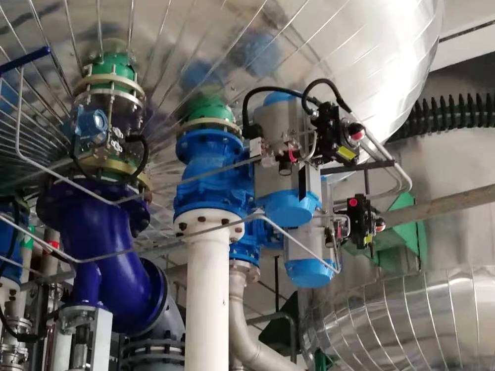
Power plant, Pacific. A power plant requested a target-type flow switch for DN50 PN16 pipe, covering 1,200 to 10,000 L/h, alarming at 81 L/min and again at 76 L/min. On a P&ID, two trip levels on one line like this are normally tagged FSL and FSLL, and each needs its own contact on the wiring diagram.
Common drawing errors
- Drawing the running state. The contact is shown closed because “it is closed when the pump runs”. Draw it at no flow.
- Tag without a set point. FSL tells you the direction, not the value. The instrument index or data sheet must carry the set point, rising or falling, and the deadband.
- FSL used for a software alarm. If there is no field switch, the tag is FAL on a flow transmitter loop, not FSL.
- NO and NC from the plant point of view. A purchase order that says “normally closed during operation” will be read as shelf state by the vendor. Write “closes on rising flow” or “opens on falling flow” instead.
- Mixed symbol sets. NEMA flags and IEC qualifiers on the same sheet with no legend.
For a thermal flow switch, the contact is a relay output with the same three terminals. Our thermal flow switch rates its relay contact at 30 VDC 5 A or 250 VAC 4 A, and it needs 24 VDC power, so its wiring diagram shows a supply pair as well as the contact.
FAQ
What is the symbol for a flow switch?
On a P&ID it is a circle tagged FS, or FSL and FSH for low and high trips. On a ladder or schematic diagram it is a switch contact with a small flag hanging from the blade, drawn in the no-flow state, either normally open or normally closed.
What are the symbols on a switch?
Switch terminals are marked C or COM for common, NO for normally open and NC for normally closed. NO is open and NC is closed when the switch is at rest, which for a flow switch means no flow through the pipe.
What is an IEC symbol?
It is a graphical symbol from IEC 60617, the international library used on European and many Asian electrical drawings. A flow switch is shown there as a normal contact combined with the qualifier S00197, “actuator (actuated by fluid flow)”.
Where is the flow switch located?
On a P&ID it sits on the process line it watches, usually as a field-mounted circle with no line through it. Physically it goes in a straight run of that pipe, often on a pump discharge, a chiller loop or a sprinkler riser.
Request a quote
Send us the P&ID tag, the line size, the fluid and temperature, the set point with its direction, and the contact your control circuit needs. Tell us the application and we configure one unit, not a shelf part. Reach our application engineers or use the form below.
Written and technically reviewed by Wu Peng and the Instranova engineering team.