By Wu Peng, Senior Process Instrumentation Engineer · Last reviewed August 6, 2026
An active 4-20 mA output supplies the power for the loop and regulates the current. A passive output only regulates the current; the power has to come from somewhere else, usually the receiving input or an external 24 VDC supply. Every working loop follows one rule: exactly one device supplies the power, and everything else behaves as a load.
That single rule settles almost every wiring question these two words cause. It also explains the two classic failures: put two power sources on one loop and the reading goes wrong; connect none and the loop sits dead at 0 mA. This guide defines the terms and maps them to 2-wire, 3-wire, and 4-wire devices. It then gives the multimeter test that identifies each side in two minutes, and the fixes when output and input do not match.
Contents
- What the terms mean
- Wire count mapping
- The multimeter test
- Matching output to input
- When loops conflict
- Fixing a mismatch
- Reading the datasheet
- FAQ
What the terms mean
Active and passive describe one thing: which end of the pair drives the loop voltage. An active output behaves like a current source with its own internal supply. Wire it to a plain input resistor and current flows with nothing else connected. A passive output behaves like an adjustable valve: it throttles whatever current an external voltage pushes through it, and with no external voltage nothing flows at all.
The same words apply to the receiving side. An active input, sometimes called a powering or transmitter-supply input, puts its own excitation voltage on the terminals, typically 24 VDC, expecting a passive device on the other end. A passive input is just a measuring resistor, commonly around 250 Ω, expecting the other end to drive the current.
Confusion starts because some pages use active and passive for the instrument, others for the analog input card. Both usages are fine; they describe the two ends of the same pair. What matters is the pairing: a 4-20 mA loop is a series circuit, and a series circuit needs one source, no more and no fewer.
Wire count mapping
Wire count predicts the output type well enough to start, as long as you treat it as a first guess rather than a law.
| Wires | Output type | Notes |
|---|---|---|
| 2-wire | Passive (loop powered, sinking) | One pair carries power and signal; needs an active input or an external supply |
| 3-wire | Active, referenced to common | Supply, signal, and shared common; output rides on the supply, so ground offsets show up in the reading |
| 4-wire | Usually active; some passive or selectable | Separate power pair; the 4-20 mA pair can be sourcing or sinking, so check the datasheet |
Sourcing = active, sinking = passive. Confirm per device; several 4-wire designs are switchable between the two.
The row people get wrong is the last one. You will see the claim that every 3-wire and 4-wire transmitter has an active output. It is not reliable.
Passive 4-wire outputs exist precisely because many control systems ship with loop power built into every analog input, so those inputs only accept loads. A mains-powered flow meter with a sinking output is a normal, catalog-standard product, and some models switch between sourcing and sinking with a jumper or a menu setting. The wire count tells you where the power supply is; only the datasheet tells you what the output does.
The multimeter test
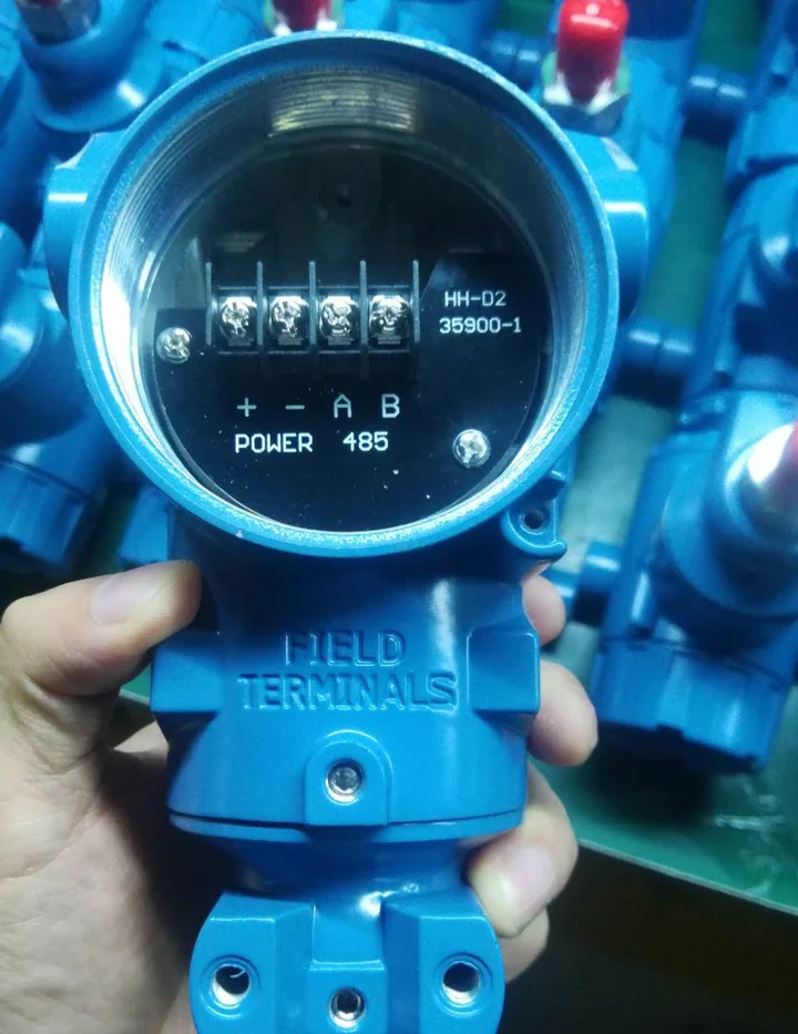
When the documentation is missing or ambiguous, a multimeter settles it. Disconnect the signal pair at the receiving end so the loop is open, then measure DC volts:
Across the field device’s two output wires. A reading around 12 to 24 VDC means the output is active; it is driving voltage on its own. A reading near zero means the output is passive and is waiting for the loop to power it.
Across the input terminals of the receiver. Around 24 VDC means the input is active and supplies excitation. Near zero means the input is a plain measuring resistor, so the other end must do the driving.
Exactly one of the two measurements should show voltage. If both do, you have found your fault before wiring anything.
A loop calibrator runs the same logic from its mode switch. In mA measure it reads an existing loop; in mA source it powers the loop itself, standing in for an active output. In mA simulate it throttles externally supplied current, standing in for a passive transmitter. If the loop only responds in source mode, the rest of that loop is passive; if simulate works, something else is already supplying power.
Matching output to input
Four combinations exist and the whole subject fits in one table:
| Combination | Result |
|---|---|
| Active output + passive input | Correct; the output drives, the input measures |
| Passive output + active input | Correct; the input powers the loop, the output throttles it |
| Passive output + passive input | Dead loop, 0 mA; add an external 24 VDC supply in series |
| Active output + active input | Two sources on one loop; wrong reading, possible damage |
Passive inputs are common across control systems, which is why active transmitter outputs and 2-wire loops with a separate supply both work so widely. Many cards also offer an active mode, selected per channel in configuration, so the card itself can power a 2-wire transmitter with no external supply. The two modes use different wiring diagrams, which is why the same card appears in both columns of a wiring manual. Full terminal drawings by device type are in our pressure transducer wiring diagram guide.
Application example
Alcohol loading station, Sri Lanka. A truck loading skid needed flow measurement feeding a batch controller. The request pinned the whole signal chain down before ordering: a DN80 turbine flow meter in 304 stainless steel, 24 VDC, 2-wire 4-20 mA output, local LCD readout, calibration capability, and a dedicated batch controller, which we proposed as a set. A 2-wire meter is a passive output by construction, so specifying the supply and the receiver together meant the one-power-source question was settled on the order sheet instead of at commissioning.
When loops conflict
The passive-passive case is the simpler failure. With no source anywhere, the loop reads 0 mA and looks like a broken wire. The fix costs one power supply: break the loop and insert 24 VDC in series, positive toward the transmitter’s positive terminal.
The active-active case is the one that costs money. Two supplies on one series loop either stack or oppose, depending on how the polarities land. Stacked, the loop can see close to 24 + 24 = 48 V. A transmitter rated for a 45 V maximum supply is now past its limit, and the current regulator burns the excess as heat.
Opposed, the two regulators fight and the current never settles at the value either end is commanding; the reading pegs high, pegs low, or wanders. Whichever end has the lower voltage rating carries the risk, and on the input side that is often a fraction-of-a-watt sense resistor that was never meant to drop tens of volts.
A less obvious version of the same mistake is adding a loop supply to a loop that already has one, for example wiring an external 24 VDC in series with an input card channel already configured to provide excitation. The loop math for how much voltage a healthy loop actually needs, device by device, is worked through in our loop-powered devices guide, with the numbers in the 4-20 mA calculator.
Fixing a mismatch
Requests for an active-to-passive converter cross my desk regularly, and most of them dissolve on inspection. An active output feeding a passive input is the correct pairing; it needs a wire, not a converter. Check the input card’s manual before buying anything: in many cases the card is passive and the loop already works.
Three situations do need extra devices or configuration changes. First, active output into an active input: either reconfigure the input channel to its passive mode, or place a loop isolator in between, wired so the isolator’s input is passive toward the transmitter and its output is passive toward the powered input. Second, passive into passive: add the external supply, nothing more.
Third, ground problems on 3-wire and mains-powered devices: when the transmitter’s common and the control system’s common sit at different potentials, the offset adds straight into the signal, and an isolator breaks the path. Signal isolators and their close relative, the splitter, are covered in detail in our 4-20 mA signal splitter and isolator guide. Look for HART pass-through when ordering one: an isolator without it strips digital communication off the loop.
If the receiving end wants a voltage signal rather than current, that is a different conversion entirely, handled with a precision resistor as described in converting 4-20 mA to 0-10 V.
Reading the datasheet
Datasheets rarely print the words active and passive. They say the same things in catalog language:
| Datasheet phrase | What it tells you |
|---|---|
| Loop powered, 2-wire | Passive output |
| External supply required | Passive output |
| Maximum load 600 or 750 Ω | Active output; it drives a load |
| Sink/source selectable | Configurable output; set it before wiring |
| Supports 2-wire transmitters (input spec) | Active input; it supplies excitation |
| Input resistance 250 Ω (input spec) | Passive input; something else must drive |
When a project mixes instruments from several suppliers, this translation step is worth doing once, on paper, for every loop. Our transmitters ship with the output type stated plainly on the datasheet and the wiring diagram matched to it; if the loop drawing is unclear, send it with the inquiry and we will mark up which end powers what.
FAQ
What is the difference between active and passive mA?
An active mA signal comes from a device that powers the loop itself and regulates the current. A passive mA signal comes from a device that only regulates current supplied by an external source, such as a powering input card or a separate 24 VDC supply.
Can you split a 4/20 mA signal?
Not by wiring two inputs in parallel; a current loop is a series circuit. You can wire a second passive receiver in series if the loop voltage budget allows, or use a signal splitter that drives two isolated outputs from one input.
Is a 4/20 mA signal AC or DC?
DC, always. The loop carries a direct current between 4 and 20 mA driven by a DC supply, typically 24 VDC. Any AC on the pair is noise, and HART communication rides on the DC loop as a small audio-frequency signal without changing its DC value.
Why is 4/20 mA preferred to a 0-20 mA signal?
Because 4 mA is a live zero. A healthy loop never reads below 4 mA, so a broken wire or dead device reads 0 mA and is instantly distinguishable from a legitimate low measurement. The full reasoning is in our 4-20 mA current loop guide.
Request a quote
Send us the instrument type, the receiving system, and who you expect to power the loop, and we will configure the output side to match: 2-wire passive, active, or with an isolator in between. Tell us the application and we configure one unit, not a shelf part. Reach our application engineers or use the form below.
Written and technically reviewed by Wu Peng and the Instranova engineering team.