By Wu Peng, Senior Process Instrumentation Engineer · Last reviewed October 12, 2026
A flow switch is an instrument that changes the state of an electrical contact when flow in a pipe or duct rises above, or falls below, a set point. It does not report a flow rate. Its output is a simple flow or no-flow signal for a pump starter, a burner control, an alarm panel or a PLC input. Vendors also call it a flow detector; in fire protection the same job is done by a waterflow detector.
That signal protects a lot of equipment. Without it a pump can run dry, a boiler or chiller can start with no water moving, and a sprinkler system cannot raise an alarm when a head opens. This guide covers how a flow switch works, the main types, set points that do not chatter, fail-safe wiring, and where each type gives trouble.
Contents
- How it works
- Flow switch types
- Switch or meter
- Choosing the set point
- Wiring and contacts
- Common applications
- Installation and testing
- FAQ
How it works
Every flow switch has three parts: a sensing element that reacts to the moving fluid, a switching element that changes state, and an adjustment that sets where the change happens. In a mechanical switch the fluid pushes on something. A paddle or vane is deflected, a piston is lifted, or a target plate is dragged, and a magnet or lever operates a sealed contact.
A thermal switch has no moving parts. One probe is heated and a second reads the fluid temperature. Moving fluid carries heat away from the heated probe, so the temperature difference between the probes shrinks as flow rises. The electronics trip the output when that difference crosses the set value.
All of them switch at two different flows. The contact actuates on rising flow at one point and resets on falling flow at a lower point. That gap is the deadband (vendors also call it the differential), and it is deliberate: without it the contact would chatter every time flow hovered at the set point.
The sketch uses published data. Johnson Controls lists these points for its F61 paddle switch in 1 in pipe at the minimum setting: it actuates at 4.20 gpm on rising flow and resets at 2.50 gpm on falling flow. Set the same switch to maximum and the two points close to 8.80 and 8.50 gpm.
Flow switch types
The sensing principle decides which fluids a switch tolerates and how low it can switch. The table compares the common types; the right-hand column is where each one usually gives trouble in service.
| Type and sensing | Typical use | Watch for |
|---|---|---|
| Paddle or vane flow deflects a blade inserted through a tee |
Water and glycol loops, pump and chiller proving, lines up to 8 in | Fibers and debris, high velocity, downward vertical flow |
| Piston or shuttle flow lifts a magnetic piston past a reed switch |
Small lines, low flows, lubrication and cooling circuits | Iron particles collecting on the magnet |
| Thermal dispersion heat loss from a heated probe |
Liquids and gases, dirty water, no moving parts wanted | Slower response, set point depends on the fluid |
| Variable area float in a tapered tube trips a contact at a height |
Very low flows, local reading plus alarm | Most designs must be mounted vertically |
| Target drag force on a plate in the stream |
Higher pressure and temperature process lines | Set point shifts with fluid density |
| Sprinkler waterflow vane in the riser plus an adjustable retard |
Fire alarm signaling on wet-pipe systems | Not for dry, deluge or preaction systems |
Limits summarized from vendor literature (Johnson Controls, Kobold, Gems, System Sensor). Pressure, temperature and set-point range vary by model; confirm per datasheet.
Paddle switches are common in building services and get a page of their own: the paddle flow switch guide has the published set-point tables and a sizing example. For dirty or fibrous water and for gas, a thermal switch avoids the moving blade altogether.
Switch or meter
Use a flow switch when the only decision is go or stop: prove flow before a burner lights, trip a pump that has lost suction, raise an alarm. A switch costs less, needs no configuration beyond the set point, and its contact can drive a relay or interlock directly.
Use a flow meter with an alarm output when you also need the number. A transmitter lets operators see flow drifting toward the trip point before it happens, and the alarm limit can be changed in software instead of by adjusting a spring. If the line already needs a meter for control, a separate switch is often redundant.
If the protection must work even when the control system is down, keep the hard-wired switch. The flow meter types guide covers the measuring side.
Choosing the set point
Set the switch for the flow you must protect, not for the flow the pipe normally carries. For a pump, that is the minimum continuous flow from the pump curve; for a boiler or chiller, the manufacturer’s minimum water flow. Normal operating flow then has to sit well above the actuation point, so ordinary swings never cause a trip.
Gems gives a usable margin. Its guidance puts the set point at least 25% below the low end of the normal flow range, because a flow switch may hold its set point only within 10 to 20%. On a 1 gpm setting with 20% accuracy, that means a trip anywhere from 0.8 to 1.2 gpm. The paddle guide adds the vendor rules for vane length and published tolerances.
Mechanical set points are published in gpm for a given pipe size, but the blade responds to velocity. Converting helps you compare sizes: velocity v in ft/s equals 0.4085 times the flow Q in gpm, divided by the square of the bore d in inches. For 1 in Schedule 40 pipe the bore is 1.049 in:
v = 0.4085 × Q ÷ d²
0.4085 × 4.20 ÷ 1.049² = 1.56 ft/s to actuate; 0.4085 × 2.50 ÷ 1.049² = 0.93 ft/s to reset
At the minimum setting this switch therefore needs about 1.6 ft/s to prove flow and does not drop out until the water slows below about 0.9 ft/s. That is a 40% deadband, generous for pump protection and too wide for a tight low-flow alarm. The pipe velocity calculator does the conversion for other sizes.
Wiring and contacts
Most mechanical flow switches carry a single-pole double-throw (SPDT) contact: one common, one terminal that closes on rising flow and one that closes on falling flow. Choose the terminal so that the circuit is closed while flow is proven. Loss of flow then opens the circuit. So does a cut wire or a loose terminal, which means a failure you cannot see still trips the interlock.
The normally open vs normally closed guide explains the same logic for pressure switches; the “normal” state on a flow switch datasheet usually means the no-flow position. The flow switch symbol guide shows how that state is drawn on P&IDs and ladder diagrams.
Check the contact rating against the load before you wire a motor directly. Ratings vary widely. The F61 switch is rated 16 A non-inductive at 120 to 277 VAC and 125 VA for pilot circuits. The Potter VSR sprinkler switch carries 10 A at 125/250 VAC but only 2 A at 30 VDC.
Reed contacts, common in small piston and paddle switches, are rated in watts (Kobold lists 20 W for the SPDT reed in its PSR paddle switch). They should drive a PLC input or an interposing relay, never a contactor coil directly.
Common applications
Pump protection is the most common job. A switch on the discharge proves that the pump is moving liquid. If flow stays below the minimum for longer than a short delay, the starter opens before the seals and impeller overheat. The same switch can stop a pump that has lost prime or is running against a closed valve. The water flow switch guide works through set points for pump, chiller, boiler and sprinkler water service.
Boilers and chillers use a flow switch as a permissive. Water-tube and coil boilers that depend on forced circulation can use a flow sensing device in place of a low-water cutoff. The California Mechanical Code, section 904.6, requires that device to shut the boiler down when flow is too low to protect it.
Chillers use the same check to stop the compressor before a tube bundle freezes. Seal flush and cooling water to rotating equipment follow the same logic; the seal water flow meter page covers that case.
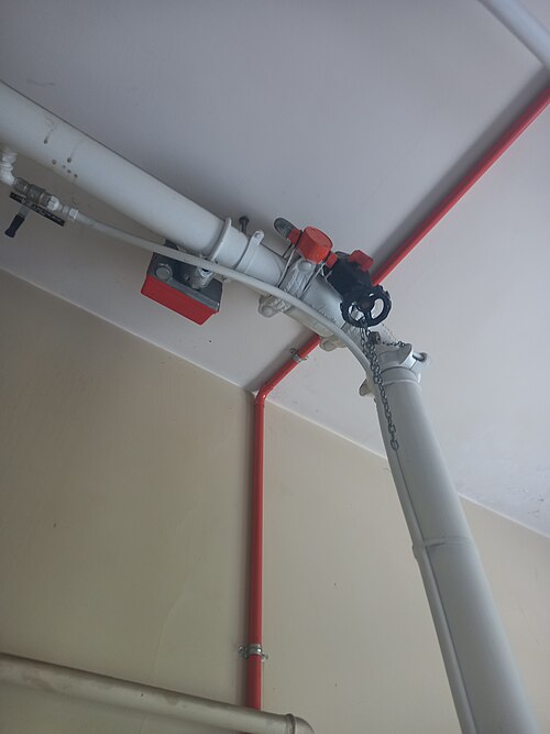
Sprinkler systems use a vane-type waterflow switch in the riser. NFPA 72 requires the initiating device to activate within 90 seconds of waterflow equal to one sprinkler of the smallest orifice in the system. The switch has an adjustable retard, typically 0 to 90 seconds, so that a pressure surge in the water main does not send a false alarm; Potter tells installers to set it at the minimum needed to prevent false alarms.
Application example
Water sector, South Asia. A customer in the water sector asked for a flow switch on a 6 in water line, with water at 5 to 50 °C (41 to 122 °F) and up to 10 bar. The request was quoted with a thermal dispersion flow switch. It senses with a fixed probe, so there is no blade to bend or to collect debris in a large line.
Our own thermal flow switch works on that principle in liquid or gas from 0 to 260 °C and up to 40 MPa. Its relay is rated 30 VDC / 5 A or 250 VAC / 4 A. Where you want a local reading as well as an alarm, a metal tube rotameter can carry an alarm contact on the same indicator head.
Installation and testing
Mechanical switches read the velocity profile, so they need straight pipe around them. Paddle switch makers typically ask for about five pipe diameters of straight pipe upstream and downstream of the switch. The straight run requirements guide explains why disturbed flow shifts the trip point.
Mount paddle switches in horizontal pipe or in vertical pipe with upward flow, never with downward flow; the published set points assume horizontal pipe. Match the arrow on the body to the flow direction, and keep the blade clear of the pipe wall. The paddle installation rules list the vendor details.
Test the switch with the process, not only with a meter on the contacts. Close a downstream valve slowly and note where the contact drops out, then open it and note where it actuates. If a mechanical switch fails to reset at no flow, look for debris on the blade or magnet first, then check whether the spring was backed off below the factory setting.
FAQ
What is a flow switch used for?
A flow switch confirms that fluid is moving and acts when it is not. It stops a pump that has lost flow, keeps a boiler or chiller from running without water, proves fan airflow in HVAC ducts, and raises the alarm when a sprinkler head opens. It reports flow or no flow, not a rate.
How does a flow switch work?
Moving fluid acts on a sensing element: it deflects a paddle, lifts a piston, or cools a heated probe. When that effect crosses the set point, a contact changes state. Because the reset point sits below the actuation point, the output does not chatter when flow hovers near the setting.
Is a flow switch the same as a pressure switch?
No. A pressure switch responds to pressure, and a line can hold full pressure with nothing moving, for example against a closed valve or a deadheaded pump. A flow switch, or a flow meter, proves that fluid is moving, which is why pump and boiler flow interlocks use one.
Are flow switches normally open?
Most mechanical flow switches carry an SPDT contact, so both a normally open and a normally closed terminal are available. “Normal” means the no-flow state. For protection, use the contact that is made only while flow is present; then a lost flow and a cut wire both trip.
How do I know if my flow switch is bad?
Run the process through the set point and watch the contact. A bad switch stays made with no flow, never makes with good flow, or trips at a flow far from its setting. Debris on the paddle or magnet, a bent blade, and burned contacts from an oversized load are the usual causes.
Request a quote
Send us the fluid, pipe size, the minimum flow you need to protect, normal flow, pressure and temperature, and what the contact must drive. We will tell you whether a thermal switch fits, or whether a meter with an alarm output is the better tool. Tell us the application and we configure one unit, not a shelf part. Reach our application engineers or use the form below.
Written and technically reviewed by Wu Peng and the Instranova engineering team.