By Wu Peng, Senior Process Instrumentation Engineer · Last reviewed October 13, 2026
A water flow switch is a flow switch installed in a water line to prove that water is moving. When flow rises past or falls below its set point, it changes a contact for a fire alarm panel, a pump starter, a chiller controller or a boiler burner. It gives a yes or no answer, not a flow rate.
The same name covers four different jobs: the vane switch on a sprinkler riser, the low-flow trip on a pump, the proof-of-flow switch on a chiller, and the flow permissive on a boiler or water heater. This guide covers all four, plus drinking-water materials, sensing types and testing.
Contents
- Four water services
- Sprinkler waterflow switches
- Pump protection
- Chiller evaporator loops
- Boilers and heaters
- Potable water parts
- Choosing the type
- Mounting and testing
- FAQ
Four water services
Begin with the water system. The table shows what the contact has to prove in each water service and where the rules come from.
| Service | What the switch proves | Set by |
|---|---|---|
| Sprinkler riser | Water is flowing to an open sprinkler; sends an alarm | NFPA 13, 25 and 72; listed device |
| Pump discharge | The pump is above its minimum flow; trips the starter | Pump curve and datasheet |
| Chiller loop | Evaporator or condenser water is moving before the compressor runs | Chiller maker’s manual |
| Boiler or heater | Water is circulating before and while the burner fires | Mechanical code and burner control |
A sprinkler switch is life-safety equipment; the other three are process devices.
The flow switch overview explains the sensing types and the deadband; this guide covers what changes with the water service.
Sprinkler waterflow switches
In a wet-pipe sprinkler system the waterflow switch is a vane device saddle-mounted on the riser or at a floor control assembly. When a sprinkler opens, the moving water deflects the vane and, after a delay, the switch closes a contact on the fire alarm panel. Fire alarm panels and codes call that signal the waterflow alarm.
NFPA 72 (2016 edition, 17.12.2) sets a time limit: the initiating device must operate within 90 seconds once the flow reaches what a single sprinkler with the smallest orifice in the system would discharge. Tyco’s Model TF, as one example, publishes a signal flow sensitivity of 4 to 10 gpm (15 to 37 L/min) and an adjustable retard of 0 to 90 seconds.
The retard is there because a pressure surge in a wet system moves water briefly without any sprinkler open. A vane with no delay would report every surge from the water main as a fire. Set the retard long enough to ride through surges, while staying inside the 90 second limit.
Three limits separate these switches from process flow switches:
- Wet pipe only. A vane switch belongs in a wet-pipe system. Dry-pipe, preaction and deluge systems use a pressure-type waterflow switch instead, because the water arriving after the valve trips can damage a vane.
- Cold water only. The Model TF is rated 32 to 120 °F (0 to 49 °C). A sprinkler vane is not a substitute on a hot water loop.
- Alarm, not supervisory. The waterflow switch sends an alarm signal. The tamper switch on a control valve sends a supervisory signal when someone starts closing the valve, within two turns of the handwheel or one fifth of its travel.
For a sprinkler riser, buy a vane switch listed for fire protection and have the fire alarm contractor install it. Our thermal switch, described below, lists no fire-protection approval, so it is not a substitute. Measuring what a fire pump delivers during its flow test is a meter job; see the fire pump flow meter guide.
Pump protection
A centrifugal pump that runs dry loses the water that cools its seal, and one that runs against a closed valve heats the water trapped in its casing. A switch on the discharge proves the pump is moving water and stops it when it is not. Here the set point is not a fixed industry number; it comes from the minimum continuous flow on the pump datasheet.
Switch tolerance limits how close to that minimum you can set the trip. Dwyer’s FSW-25 paddle switch, for example, lists a set point tolerance of ±25% and a repeatability of ±5%. The first is how far the real trip can sit from the nominal setting; the second is how much it wanders once set. Set the dial to the pump minimum without checking it, and the real trip may sit 25% below it, where the pump is already unprotected.
Worked example. A pump datasheet gives a minimum continuous flow of 60 gpm (227 L/min). The discharge is 3 in Schedule 40 pipe, inside diameter 3.068 in. The switch is the FSW-25 above, set by its nominal adjustment only, so its ±25% tolerance applies.
Nominal trip ≥ minimum flow / (1 − tolerance) = 60 / 0.75 = 80 gpm
At 80 gpm, the switch can trip anywhere from 60 to 100 gpm. That means normal running flow has to stay above 100 gpm, or the pump will trip while it is running normally. If the process normally runs at 90 gpm, the nominal setting alone cannot protect this pump.
Field setting gives a different result. Adjust the trip while reading flow from a reference, for example a clamp-on flow meter, and the ±5% repeatability becomes the limit instead. A trip set and confirmed at 64 gpm then stays between about 61 and 67 gpm. That protects the 60 gpm minimum and leaves room for 90 gpm running flow.
Paddle charts are usually printed in gpm for one pipe size, while thermal switches are set in velocity. Convert with v (ft/s) = 0.4085 × Q (gpm) / d² (in):
60 gpm = 2.60 ft/s · 64 gpm = 2.78 ft/s · 80 gpm = 3.47 ft/s · 100 gpm = 4.34 ft/s in 3 in Schedule 40
The pipe velocity calculator converts other sizes, and the paddle flow switch guide lists published set point tables.
Start-up needs its own logic. At the moment the starter closes there is no flow, so the low-flow contact is open. The control system has to ignore the flow switch for a short start window and arm the trip only after it ends. A thermal switch adds two delays to that window: it needs a warm-up period after power-on, and it reacts in seconds, not instantly.
Measure how long the pump takes to reach flow at commissioning, add the switch response time, and set the window from that rather than from a default. Wire the contact that is closed with flow into the run permissive, so a broken wire stops the pump instead of hiding a fault. The guide to normally open and normally closed contacts covers the labels. The flow switch symbol guide shows how that contact appears on ladder and wiring diagrams.
Chiller evaporator loops
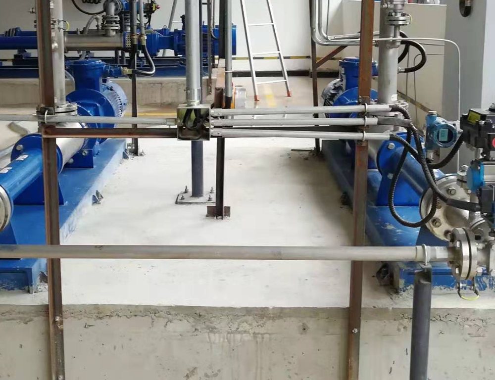
A chiller must not run its compressor without water moving through the evaporator, and the chiller maker says how to prove flow. Trane’s guidance is one example. On several of its water-cooled models the evaporator needs two forms of proof, a flow switch or differential pressure switch plus the pump starter auxiliary contacts, wired in series. On the condenser loop either one, or both, is acceptable.
The same guidance says to adjust the switch to open when water flow falls below nominal, and points to the general data table for the minimum flow of each pass arrangement. It also asks for upright mounting with at least five pipe diameters of straight horizontal run each side, away from elbows, orifices and valves. Air must be purged from the loop, or the paddle flutters. Its CH530 controller waits 6 seconds on the flow switch input before a loss-of-flow shutdown.
Check the chiller manual for the model you have; requirements differ even inside one brand. Glycol mixes change the force on a paddle and the heat transfer on a thermal probe. Recheck a switch adjusted on plain water after the glycol goes in. Measuring the cooling load takes a meter; see the BTU meter for chilled water.
Boilers and heaters
On a boiler or water heater the flow switch is a permissive in the burner circuit. On a forced-circulation boiler, a mechanical code may accept an approved flow-sensing device instead of a low-water cutoff; the flow switch overview quotes the California Mechanical Code wording.
Temperature is the first check here. A sprinkler vane rated to 120 °F does not belong on a heating loop. Read the wetted-part rating against the highest water temperature the loop can reach, including the overshoot when a pump stops and the boiler is still hot.
The second check is response: compare the switch response time, plus the warm-up time of a thermal switch, with what the burner control expects.
Potable water parts
On a drinking water line, the lead-free rules for plumbing apply to the wetted parts of a flow switch. Since January 4, 2014, the US Safe Drinking Water Act has required pipe, fittings and fixtures in drinking water systems to be lead free. That means a weighted average of no more than 0.25% lead across the wetted surfaces, and 0.2% in solder and flux.
The simple way to show compliance is third-party certification to NSF/ANSI 372 (lead content) or NSF/ANSI 61. Ask for the certificate and check that it names the model, not just the brand. A brass switch sold for industrial service may not carry it.
Lines used only for industrial processing, irrigation or other nonpotable service are exempt, so a switch on a cooling tower or process loop does not need the certificate. A 316L stainless wetted path has no lead in its alloy, but certification is still what shows compliance; the wetted parts guide compares the common materials.
Choosing the type
Once the service and the set point are known, the choice of sensing principle is usually clear.
| Type | Good for | Watch for |
|---|---|---|
| Vane | Wet sprinkler risers | Listed fire use only; cold water |
| Paddle | Clean water in 1 to 8 in pipe, no power needed | Wide tolerance; moving parts |
| Piston | Small lines and low flows; usually a magnet and reed contact | Pressure drop; dirt in the bore |
| Thermal | Large lines, hot water, no moving parts | Needs power; warm-up and seconds of response |
A vane or paddle switch is a dry contact. It needs no supply of its own and switches the voltage of the circuit it sits in, such as a fire alarm initiating circuit or a starter control circuit. A thermal switch needs power to heat its probe.
Our thermal flow switch is a thermal dispersion type for pump, chiller and boiler service. Its published ratings:
| Parameter | Specification |
|---|---|
| Principle | Thermal dispersion, heated probe plus reference probe |
| Process temperature | 0 to 260 °C |
| Working pressure | Up to 40 MPa |
| Process connection | G1/2 or G3/4 thread; others to order |
| Probe | 316L stainless steel, 48 mm standard |
| Output | Relay, 30 VDC 5 A or 250 VAC 4 A |
| Power | 24 VDC, up to 40 mA |
| Response | 1 to 10 s, typically 2 s |
| Warm-up | About 1 minute after power-on |
| Protection | IP65 |
Published values; confirm per datasheet.
Application example
Water utility, South Asia. A water utility needed flow or no-flow detection on a 6 in line carrying water between 5 and 50 °C at up to 10 bar. We quoted a thermal dispersion flow switch: an insertion probe with no moving parts in the water path.
Mounting and testing
Many water flow switch problems trace back to where the switch sits. Put it in a straight section, follow the arrow on the body, and keep it clear of elbows, valves and reducers. Follow the switch maker’s straight-run figure; Trane’s chiller guidance asks for five pipe diameters each side (see straight run requirements). Purge air so a paddle does not flutter and a thermal probe stays wetted.
Testing depends on the service:
- Sprinkler. NFPA 25 (2023, Table 13.1.1.2) calls for vane-type and pressure-type waterflow devices to be tested semiannually, and mechanical water motor gongs quarterly. The test flows water through the inspector’s test connection and checks that the panel gets the alarm in time.
- Pump, chiller and boiler. Throttle the flow down with the pump running and record the flow at which the contact trips. Then raise it again and record the reset. Compare both with the commissioning record; a trip point that has moved points to debris on the paddle, scale on a thermal probe or a bent paddle.
A sprinkler vane switch returns to normal by itself when flow stops; the alarm is cleared at the fire alarm panel. Never jumper a flow switch to get equipment running. Find out why flow is low.
FAQ
What does a water flow switch do?
It watches a water line and changes a contact when flow rises past or drops below a set point. In a sprinkler system that contact raises an alarm. On a pump, chiller or boiler it stops the equipment, or keeps it from starting, when water is not moving.
What is the difference between a tamper switch and a waterflow switch?
A waterflow switch senses water moving in the sprinkler pipe and sends an alarm signal, meaning a sprinkler may be open. A tamper switch sits on a control valve and sends a supervisory signal when the valve starts to close, warning that the system could be shut off.
Is a waterflow switch an initiating device?
Yes. In a fire alarm system the waterflow switch is an alarm-initiating device. NFPA 72 gives it 90 seconds to operate after the flow reaches the discharge of one smallest-orifice sprinkler. The panel then sounds the alarm and, where required, transmits the signal.
How do you test a water flow switch?
On a sprinkler system, open the inspector’s test connection and confirm the panel receives the waterflow alarm within the allowed time; NFPA 25 sets this test every six months for vane switches. On a pump or chiller, reduce the flow and record the trip and reset points against the setting.
What is another name for a flow switch?
Common names include flow sensor switch, flow alarm and flow indicator switch. Fire protection uses waterflow detector or waterflow alarm switch, and HVAC drawings often label it a proof-of-flow switch.
Request a quote
Send us the water service, pipe size and schedule, normal and minimum flow, water temperature and pressure, and the contact rating your control circuit needs. Tell us the application and we configure one unit, not a shelf part. Reach our application engineers or use the form below.
Written and technically reviewed by Wu Peng and the Instranova engineering team.