Flow Meters › Thermal Mass Flow Meters › Thermal Flow Switch
Thermal Flow Switch
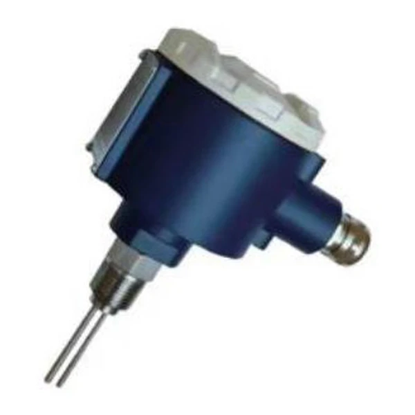
A thermal flow switch detects flow or no-flow by thermal dispersion. A heated probe and a reference probe sit in the line; flowing gas or liquid carries heat away and the temperature difference trips a relay at a set point. With no moving parts and a 316L probe, it protects pumps and lines against dry running and low flow in gas and liquid service.
- Principle: Thermal dispersion, direct gas mass flow
- No compensation: Reads mass; no T or P correction needed
- Form: Inline DN10 to DN80, insertion DN80 to DN4000
- Velocity: 0.1 to 100 Nm/s, wide turndown
- Accuracy: +/-1.5% to 2.5%
- Output: 4-20 mA, pulse, RS485, HART
Overview
A thermal flow switch proves whether fluid is moving. Two probes sit in the line, one heated and one reading the fluid temperature; flowing gas or liquid carries heat away from the heated probe, and when the velocity crosses a set point the switch trips a relay. It reports flow or no-flow, not a continuous rate, which is exactly what pump dry-run protection and low-flow alarms need.
With no moving parts, a sealed 316L probe, and a flameproof die-cast housing, the switch works in gas and liquid from 0 to 260 C and to 40 MPa, and the same instrument can be set for level or temperature alarm. When you need the actual flow rate, use a thermal mass flow meter instead.
Features
Everything here follows from one idea: read gas mass directly from heat loss, instead of reading volume and correcting it.
Direct mass, no compensation
It reads gas mass flow directly, so there is no separate temperature and pressure compensation to buy, wire, or maintain.
Very wide turndown
It reads from about 0.1 Nm/s up to 100 Nm/s, so it catches creeping flow and even gas leaks that other meters miss.
No moving parts
Nothing spins or wears, the pressure loss is negligible, and the insertion probe installs through a single tap.
Inline or insertion
An inline body suits DN10 to DN80; an insertion probe reaches DN80 to DN4000, for ducts and large gas mains.
Standard outputs and alarms
4-20 mA, pulse, RS485 Modbus, and HART, plus one or two alarm relays for high or low flow.
Wide gas range
Air, natural gas, coal gas, LPG, flare gas, hydrogen, CO2, nitrogen, and flue gas; most gases except acetylene.
Working principle
A thermal flow switch works by thermal dispersion. Two probes sit in the flow: one is heated, the other reads the fluid temperature. When fluid flows, it carries heat away from the heated probe and the temperature difference between the two probes falls; the faster the flow, the larger the cooling. The switch compares that difference with a set point and trips a relay, so it signals flow or no-flow rather than a continuous rate. With no moving parts and a sealed 316L probe, it works in gas and liquid alike.
Technical specifications
| Parameter | Specification |
|---|---|
| Measurement principle | Thermal dispersion: one heated probe and one reference probe; flowing fluid carries heat away, and the temperature difference sets the flow or no-flow point |
| Measured | Flow, level, and temperature of gas and liquid (water, air, and other gases) |
| Set point | Velocity set point by medium, with separate ranges for water and liquid, hydrocarbons, and air or gas |
| Process temperature | 0 to 260 C |
| Working pressure | 0 to 40 MPa |
| Process connection | G1/2 or G3/4 thread; others to order |
| Output | Relay contact, 30 VDC / 5 A or 250 VAC / 4 A |
| Power | 24 VDC, up to 40 mA |
| Response time | 1 to 10 s, typically 2 s |
| Preheat time | About 1 minute after power-on |
| Probe length | 48 mm standard; others to order |
| Probe material | 316L stainless steel |
| Housing | Die-cast aluminum, flameproof |
| Electrical connection | M20 x 1.5 |
| Protection | IP65 |
Set point and output
The switch trips when the flow velocity crosses a set point. The usable set-point band depends on the fluid: liquids and water carry heat away strongly, so they switch at low velocity; air and gas need a higher velocity for the same cooling, and hydrocarbons fall in between. The set point is configured for the actual medium and process connection.
| Medium | Typical set-point behavior |
|---|---|
| Water and liquid | Switches at low velocity; strong cooling gives a clear flow or no-flow signal |
| Hydrocarbons | Intermediate velocity band; set to the specific oil or solvent |
| Air and gas | Higher velocity needed; widest set-point range of the three |
The output is a relay contact rated 30 VDC / 5 A or 250 VAC / 4 A, wired to an alarm, a PLC, or a motor starter for protection.
Switch or continuous meter
A thermal flow switch gives a single flow or no-flow signal at a set point, which is all that pump protection and low-flow alarms need, and it is the lower-cost choice. When you need the actual flow rate or a total, use a thermal mass flow meter, which reads gas mass flow continuously over a wide range.
Applications
The thermal flow switch is used wherever a simple flow or no-flow signal protects equipment:
- Pump dry-run and low-flow protection on water and oil lines
- Flow proving on cooling-water, lubrication, and seal-flush lines
- No-flow alarms on gas purge, sampling, and combustion-air lines
- Confirming circulation before a heater or compressor starts
- Level or temperature high and low alarms on tanks and vessels
Application example
Challenge: A cooling-water pump needed protection against dry running, where a mechanical paddle switch had stuck and failed.
Solution: A thermal flow switch with no moving parts was set just above the minimum safe velocity and wired to the pump starter.
Result: The pump tripped on loss of flow without nuisance trips, and the sealed probe shrugged off the debris that had jammed the paddle.
Related products
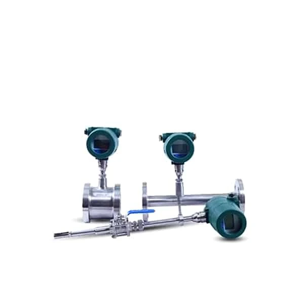 Thermal Mass Flow Meter
Continuous gas mass flow with no temperature or pressure compensation.
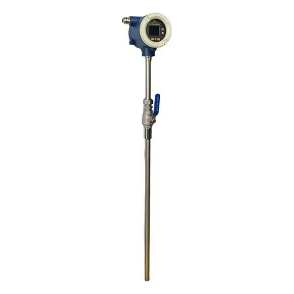 High Temperature Gas Flow Meter
Insertion airspeed probe for hot gas to 800 C; flue and exhaust gas.
FAQ
What is a thermal flow switch?
It is a flow detector that uses thermal dispersion. A heated probe and a reference probe sit in the line; flow carries heat away and the temperature difference trips a relay at a set point, signaling flow or no-flow with no moving parts.
How does a thermal flow switch work?
One probe is warmed above the fluid temperature. Moving fluid cools it, and the cooling rises with velocity. The electronics compare the temperature difference with a set point and switch a relay, so the device reports whether flow is above or below the threshold.
Can it be used on both gas and liquid?
Yes. The same switch works in gas and liquid; liquids cool the probe strongly and switch at low velocity, while gas needs a higher velocity. The set point is configured for the actual medium, and the unit can also serve as a level or temperature alarm.
Flow switch or flow meter?
Use a thermal flow switch for a simple flow or no-flow signal, such as pump protection and low-flow alarms, at lower cost. Use a thermal mass flow meter when you need the actual flow rate or a total.
Request a quote
Send us the gas, the line or duct size, the flow range, and the pressure and temperature, and we size the thermal mass flow meter and calibrate it for your gas.