By Wu Peng, Senior Process Instrumentation Engineer · Last reviewed August 4, 2026
A flow meter measures instantaneous flow rate: how much fluid is passing through the pipe right now, in units such as m³/h, L/min, GPM, or kg/h. A flow totalizer accumulates that rate over time into a cumulative quantity: liters, cubic meters, gallons, or kilograms. The flow meter answers “how fast”, the totalizer answers “how much so far”. Many instruments combine both jobs in one housing, which is why the two names get mixed up in specifications and purchase orders.
The distinction matters commercially. Billing, inventory reconciliation, batch records, and water-rights reporting are all settled on the total, not the rate. This guide works through the mechanics with real numbers. It covers analog and pulse totalization math, the P&ID tag letters that confuse many buyers, what a total’s accuracy really means, and which instrument to specify.
For the measuring technologies themselves, start with our flow meter overview.
Contents
- Rate and total
- How totalization works
- Pulse totalization
- Totalizers on P&IDs
- Accuracy of totals
- Resettable and grand totals
- Gas and steam totals
- Choosing the instrumentation
- FAQ
Rate and total
A flow rate is a snapshot with time in its unit: 15 m³/h, 250 L/min, 900 kg/h. A total is a quantity with the time already integrated out: 360 m³, 12,500 L, 21,600 kg. A total can never be expressed in L/min; if a display shows L/min, you are looking at rate, not accumulation. That single unit check resolves most of the confusion between the two terms.
A totalizing flow meter, sometimes written flow totalizer meter or flow meter with totalizer, is simply a flow meter whose electronics keep the running sum. The total shows on the display alongside the rate. A stand-alone flow totalizer is a separate indicator, panel meter, or flow computer that receives the meter’s output signal and does the accumulation externally. Both arrangements are common, and the table below shows what each one reports.
| Question | Flow meter (rate) | Flow totalizer (total) |
|---|---|---|
| What it answers | How fast is fluid moving now | How much has passed since a start point |
| Typical units | m³/h, L/min, GPM, kg/h | m³, L, gal, kg |
| Used for | Control, pump protection, alarms | Billing, inventory, batching, reporting |
| Typical signal | 4-20 mA scaled to a rate span | Pulse per fixed volume, or a summed register |
Everyday reference points: a residential water meter register and a fuel dispenser readout are both totalizers; a car speedometer is a rate instrument and the odometer next to it is the totalizer.
How totalization works
Totalization is integration: the total is the area under the rate curve. When the rate is steady, the math collapses to one multiplication.
Total volume = flow rate × elapsed time
A line held at 12 mA on a 4-20 mA range spanned 0 to 30 m³/h reads (12 − 4) / 16 × 30 = 15 m³/h. Run steady for 24 hours, the totalizer adds 15 × 24 = 360 m³.
Real flows are not steady, so electronic totalizers sample the rate and add a slice on every update. A totalizer sampling once per second converts the rate to per-second units and accumulates. At 15 m³/h it adds 15 / 3600 = 0.00417 m³ each second; 86,400 samples later the register shows the same 360 m³. Any instrument that accepts an analog input can do this, and it is worth stating plainly.
A claim you will meet in the field says a meter can only be totalized through a pulse output. That is not correct: analog-input rate totalizers integrate the 4-20 mA signal directly. The pulse route is usually the more accurate one, as the next section shows, but it is not the only one.
One practical trap in PLC totalization: do the division in floating point. A rate of 100 L/h is 0.0278 L/s. If the conversion runs in integer math, that slice truncates to zero and the total never moves, even though flow is real. The symptom is a total that stalls at low rates and catches up only when flow is high; the fix is a floating point accumulator or, better, a pulse input.
Unit handling for these conversions is covered in our flow rate units guide.
Pulse totalization
Most industrial meters offer a pulse output, and for totals it is the preferred path. The meter emits a fixed number of pulses per unit volume, published as the K-factor. Totalizing is then counting, not sampling.
Total = pulse count / K-factor
A turbine flow meter with K = 450 pulses per liter that has delivered 45,000 pulses has passed 45,000 / 450 = 100 L.
Larger meters and batching systems often use a scaled pulse instead: the electronics divide the raw pulse train so that one output pulse equals a round volume, for example one pulse per 10 L. A counter reading 1,250 scaled pulses means 12,500 L, and the counter can be a cheap electromechanical register, a PLC high speed counter input, or a panel totalizer. Because every pulse represents a fixed volume, a pulse-counted total tracks the meter exactly: there is no sampling interval to introduce error between the meter and the register.
The K-factor itself is a calibration quantity: if it is re-determined on a prover or bench, the totalizer scaling must be updated with it. See our flow meter calibration guide for how K-factors are verified.
Totalizers on P&IDs
Buyers often meet the distinction for the first time on a P&ID, where the flow meter and the totalizer carry separate tag bubbles. Our P&ID instrumentation symbols guide explains the letter code. The letters follow ISA-5.1: the first letter F means flow, and the succeeding letter Q means integrate or totalize. Reading the common combinations:
| Tag | Meaning |
|---|---|
| FE | Flow element: the primary device in the line (orifice plate, turbine rotor, magnetic tube) |
| FT | Flow transmitter: converts the element’s response to a signal, usually 4-20 mA |
| FI | Flow indicator: displays rate |
| FQ | Flow totalizer: integrates the flow signal to a quantity |
| FQI | Indicating totalizer: displays the accumulated quantity |
| FIT / FQIT | Indicating transmitter / indicating totalizing transmitter: combined functions in one device |
So a drawing showing FE, FT, and FQ as three bubbles describes one measurement: an element in the pipe, a transmitter on it, and a totalizing function downstream, even when all three live in a single housing.
Accuracy of totals
A total inherits the meter’s rate error, and the accuracy statement’s reference matters far more over a month than it does on a single reading. A meter specified as a percent of reading contributes the same relative error at any rate. A meter specified as a percent of full scale gets relatively worse as flow drops, and the total accumulates that penalty.
Take a 30 m³/h span meter run at a steady 6 m³/h for a 30-day month, which delivers 6 × 24 × 30 = 4,320 m³. At ±0.5% of reading the total is good to about ±21.6 m³. At ±0.5% of full scale the fixed ±0.15 m³/h band is ±2.5% of the true rate at this operating point. The monthly total can then be off by ±108 m³: five times worse from the same headline number.
Two more contributors are specific to totalization. First, low flow cutoff: meters suppress readings below a threshold to avoid totalizing noise at zero flow, so persistent dribble below the cutoff never reaches the register. That is desirable for control and a real loss for reconciliation, so set the cutoff deliberately. Second, the signal path: a total computed from the 4-20 mA signal adds the analog conversion and sampling errors on top of the meter error, while a pulse-counted total carries only the meter error.
When the total is the commercial quantity, take the pulses.
Resettable and grand totals
Practical totalizers keep more than one register. The resettable total, often called batch or trip total, is zeroed at will: per batch, per shift, per delivery. The grand total, also called accumulated total, cannot be reset from the front panel and plays the role of the odometer. Reconciliation and audit work is done by subtracting an earlier reading from a later one, so nobody’s reset habit can erase throughput history.
Utility registers work the same way, which is why regulators ask for reading pairs, later minus earlier, rather than trusting a resettable display.
Register sizing is worth a glance at specification time. An 8-digit register counting in liters rolls over at 99,999,999 L, about 100,000 m³; a line moving 4,320 m³ a month would wrap it in under two years. Choosing a larger display unit, m³ instead of L, or a register with more digits keeps rollovers rare, and noting the rollover point in the log keeps the subtraction correct when one finally happens.
Battery-backed or non-volatile storage of the registers matters too: a totalizer that forgets its count on power loss is useless for accounting.
Gas and steam totals
For liquids, a volumetric total is usually the commercial answer. For gases it is not, because the amount of gas in one operating cubic meter depends on pressure and temperature. At 7 barg and unchanged temperature, one operating m³ holds roughly 7.9 times the gas of one atmospheric m³, so an uncorrected total in operating volume is close to meaningless for energy or billing. Gas totalization therefore runs through pressure and temperature compensation to standard volume, or uses a meter that reads mass directly.
A rotary gas meter pairs the mechanical counter with an electronic corrector for exactly this reason, and a thermal mass flow meter totalizes standard volume without external compensation because its sensing principle responds to mass flow.
Steam totals are normally kept in mass, kilograms or tonnes, because steam energy content follows mass, not volume. That means density compensation from pressure and temperature ahead of the totalizer. The difference between mass and volumetric accounting, and when each is the right basis, is covered in our mass flow vs volumetric flow guide.
Choosing the instrumentation
The choice is less about totalizer versus flow meter and more about where the totalizing function should live. Four arrangements cover nearly every case:
| Arrangement | When it fits |
|---|---|
| Meter with built-in totalizer | Default for most process lines. A magnetic flow meter or an oval gear flow meter shows rate and total at the line and still outputs pulse or 4-20 mA |
| Panel rate/totalizer | Control room or skid display for a meter that has no readout, plus alarms, retransmission, and batch relays |
| Field totalizer display | Remote or hazardous locations; loop-powered and explosion proof versions exist for lines with no local power |
| Flow computer / corrector | Gas and steam totals needing pressure and temperature compensation, multi-stream sites, custody metering |
Where the total is the product being sold, the meter class matters as much as the arrangement: an ultrasonic water meter is built around metering accuracy classes for long, unattended accumulation. For a survey of measuring technologies behind all of these, see the flow meter types guide.
Application example
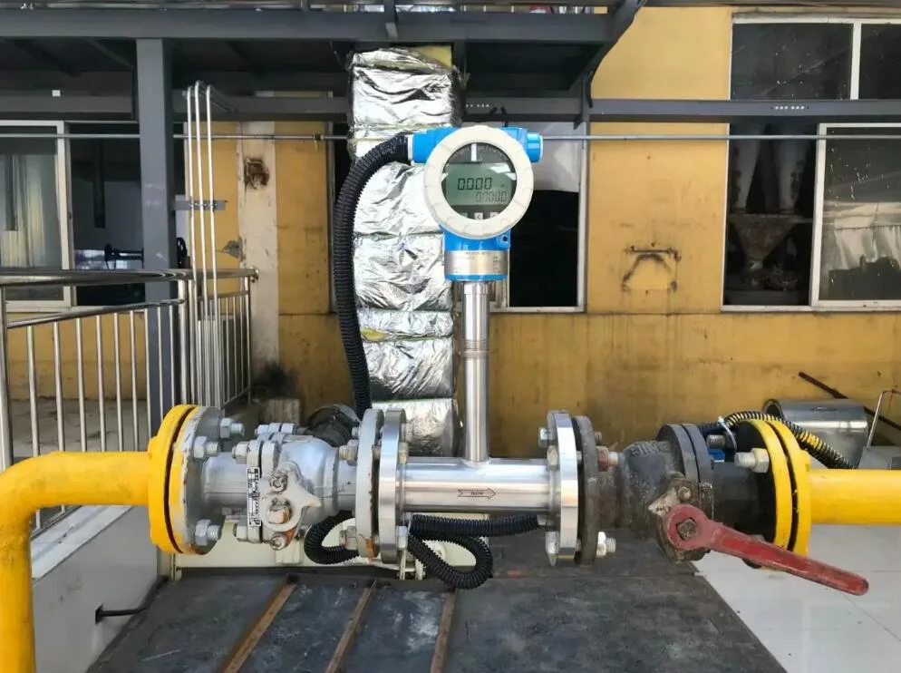
Automation integrator, India. The panel needed rate, total, alarms, and a repeat of the flow signal from a single measurement. We proposed a 96 × 96 mm panel rate/totalizer taking one 4-20 mA flow input, with a 4-20 mA retransmission output, two alarm relays, and RS485, paired on the line with a vortex or differential pressure flow meter. One panel instrument covers the display, the totalization, and the outputs the control system needs.
FAQ
What is a totalizer in a flow meter?
It is the function or register that accumulates measured flow into a cumulative quantity. The meter measures rate in units like m³/h. The totalizer integrates that rate over time and displays total volume or mass, such as m³ or kg, since the register started or was last reset.
What is a totalizer used for?
Anywhere the commercial or record-keeping quantity is “how much”, not “how fast”: water and fuel billing, chemical batch records, inventory reconciliation, energy accounting, and regulatory reporting of extracted or discharged volumes. Control systems use rate; accounting runs on totals.
How does a flow totalizer work?
Two ways. It can integrate an analog rate signal, sampling the 4-20 mA input and adding rate times interval on each update. Or it counts pulses from the meter, where each pulse represents a fixed volume set by the K-factor. Pulse counting tracks the meter exactly and is preferred for commercial totals.
How to calculate flow totalizer?
For steady flow, multiply rate by time: 15 m³/h for 24 hours totals 360 m³. For varying flow, sum rate times sample interval over the period. For pulse outputs, divide the pulse count by the K-factor: 45,000 pulses at 450 pulses per liter is 100 L.
Request a quote
Tell us the line size, fluid, flow range, and whether the total is for control, inventory, or billing, and we will propose the meter and totalizing arrangement together. Reach our application engineers or use the form below.
Written and technically reviewed by Wu Peng and the Instranova engineering team.