By Wu Peng, Senior Process Instrumentation Engineer · Last reviewed July 21, 2026
Home › Tools › Pipe Pressure Drop Calculator
This calculator estimates the friction pressure drop in a straight pipe from flow rate, inside diameter, length, and pipe material. It works in metric and US units, and covers water at 20 °C or 60 °C plus any custom fluid. It reports velocity, Reynolds number, friction factor, and the loss in kPa, psi, bar, and meters of water. The math is the Darcy-Weisbach equation, Δp = f (L/D)(ρv²/2), with the friction factor solved automatically from the Swamee-Jain correlation.
The result is the major (friction) loss of straight pipe only; add fittings and valves separately as equivalent lengths. If you first need the velocity or a minimum bore for a target velocity, start with the pipe velocity calculator.
Calculator
Pipe pressure drop (Darcy-Weisbach)
Results update as you type. Straight-pipe friction loss only, incompressible flow; for gases use it only when the drop stays below about 10 percent of the absolute line pressure.
Method and formula
The calculator converts your flow rate to velocity from the pipe cross section, computes the Reynolds number, and picks the friction factor for the flow regime. Laminar flow (Re below 2,300) uses f = 64/Re. Turbulent flow uses the Swamee-Jain explicit form of the Colebrook equation, which needs the pipe roughness; that is why the material selector matters. A smooth plastic pipe loses noticeably less pressure than galvanized steel at the same velocity.
Δp = f × (L / D) × (ρ × v² / 2)
A classic cross-check: 60 US GPM of cold water through 2-inch schedule 40 steel pipe (52.5 mm bore) loses about 2.8 psi per 100 ft. Published friction tables put that line at 2.7 to 3 psi per 100 ft, and the calculator reproduces it.
Worked example
A skid needs 12 m³/h of cooling water through 50 m of DN50 steel pipe (52.5 mm bore). The calculator gives:
- Velocity = 12 / 3600 / (π × 0.0525² / 4) = 1.54 m/s
- Reynolds number = 80,500 (turbulent), friction factor f = 0.0223
- Pressure drop = 0.0223 × (50 / 0.0525) × (998 × 1.54² / 2) = 25.2 kPa (3.7 psi)
That is about 2.6 m of pump head spent on 50 m of pipe before a single valve or elbow is counted. Run the same case in copper and the loss falls to roughly 21 kPa. Step the bore up to DN65 and it falls to about 10 kPa, less than half, because velocity falls with the square of the bore and the loss with the square of velocity.
Application example
Food plant, Jordan. A bakery line needed two meters for precise batch water dosing on a 1-inch line at up to 4,000 kg/h. The process engineer capped the whole metering drop at 5 to 10 kPa. At 4 m³/h a 1-inch bore already runs 2 m/s and loses about 1.9 kPa per meter of straight steel pipe. The budget left no room for a high-loss meter. We proposed a Coriolis mass flow meter sized so its pressure loss stayed inside the window at full flow, with 0.5 percent accuracy on mass.
Pressure loss budgets
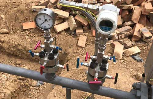
Every instrument you put in the line spends part of the pump or compressor head, so treat pressure drop as a budget. Orifice plates are the most expensive item on that budget; they recover only part of the differential they create. If the loss matters, measure flow with a venturi tube, a V-cone, or an averaging pitot tube. Each takes a fraction of an orifice loss on the same line. The pressure side of that trade is explained in flow rate and pressure relationship.
Related guides and tools
If you want the method behind this tool explained step by step, read the guide on how to calculate pressure drop in a pipe. The pipe velocity calculator answers the sizing question that usually comes first: what bore keeps the velocity inside recommended limits. The pressure unit converter moves the result between kPa, psi, bar, and water column with proper significant figures. For the physics behind the numbers, see flow rate and pressure relationship. For choosing units on the flow side, use the flow rate units guide.
The friction factor inside this calculator switches on the Reynolds number. To check Re on its own, with fluid presets and a regime verdict, use our Reynolds number calculator.
FAQ
How much pressure drop per 100 ft of pipe?
It depends on velocity, bore, and roughness. Cold water at 60 US GPM in 2-inch schedule 40 steel loses about 2.8 psi per 100 ft; a 3-inch line at the same flow loses under half a psi. Compressed air mains are sized tighter still, usually for 0.3 to 0.5 psi per 100 ft.
What is the rule of thumb for pipeline pressure drop?
Common design practice keeps liquid lines between roughly 1 and 4 psi per 100 ft (about 2 to 9 kPa per 10 m) and holds velocities near 1 to 3 m/s for water. Suction lines and pressure-drop-sensitive services sit at the low end. Rules of thumb are for first-pass sizing; check the actual number with the calculator before you lock in a pipe size.
Request a quote
If the pressure drop you calculated has to feed a flow measurement, we supply DP flow elements sized to your loss budget along with the matching differential pressure transmitters. Tell us the application and we configure one unit, not a shelf part. Reach our application engineers or use the form below.
Written and technically reviewed by Wu Peng and the Instranova engineering team.