By Wu Peng, Senior Process Instrumentation Engineer · Last reviewed August 11, 2026
Home › Tools › Reynolds Number Calculator
This Reynolds number calculator works three ways: enter a flow rate in m³/h, L/min, or US GPM with the pipe bore, enter a velocity directly, or set a target Reynolds number and get the minimum flow that reaches it. Every mode uses the pipe-flow definition Re = ρ · v · D / μ, reports the flow regime, and checks the result against the Reynolds number floors that matter for flow meter selection.
The calculator covers flow inside pipes and tubes. Reynolds numbers for airfoils, submerged bodies, and open channels use different characteristic lengths and different transition values, and this tool does not apply to them. For what the number means for pressure loss, the friction-factor side of the story is in our pressure drop formula guide.
Calculator
Reynolds number calculator
Results update as you type. Circular pipes running full, Newtonian fluids; preset properties are typical values at the stated temperature. Results are engineering estimates, not a calibration.
Formulas used
The Reynolds number compares inertial forces to viscous forces. For flow in a circular pipe it takes the inside diameter as the characteristic length:
Re = ρ · v · D / μ = v · D / ν
with density ρ in kg/m³, velocity v in m/s, diameter D in m, dynamic viscosity μ in Pa·s, and kinematic viscosity ν = μ/ρ in m²/s. When you know the flow rate instead of the velocity, substitute v = 4Q/(πD²) and the equation becomes:
Re = 4 · ρ · Q / (π · D · μ)
Working in US units, the same physics condenses into the shortcut Re = 3160 · Q · SG / (d · μ) with Q in GPM, d in inches, and μ in centipoise; the constant 3160 carries all the unit conversions. A classic sanity check: water at 1 m/s in a 100 mm line is close to Re = 100,000. The calculator returns 99,621 with water at 20 C, which is that rule of thumb with the fluid properties made explicit.
Flow regimes
Below about Re = 2,300 the flow is laminar: fluid moves in ordered layers with a parabolic velocity profile. Above about 4,000 it is turbulent, with eddies, mixing, and a flatter profile. Between the two the flow is transitional and can flip between behaviors, which is why designers avoid sizing equipment into that band.
Published limits differ from source to source: 2,000, 2,100, and 2,320 all appear as the laminar limit, and 2,900 to 4,000 as the turbulent onset. None of them is wrong. The transition is not a sharp switch; it happens intermittently over a range that depends on inlet conditions, pipe roughness, and vibration, and each reference rounds that reality to a different convenient number. Treat 2,300 and 4,000 as the working band, and do not expect two textbooks to agree to three digits.
Reynolds number and meters
The practical reason a process engineer computes Re is that several flow measurement technologies stop performing below a Reynolds number floor. The published guidance:
| Technology | Reynolds number guidance |
|---|---|
| Standard orifice plate | ISO 5167-2 does not cover pipe Re below 5,000, and the floor rises with the beta ratio |
| Classical venturi | Machined venturis are characterized for roughly Re 200,000 to 1,000,000 per ISO 5167-4 |
| Vortex | Accuracy typically guaranteed above about Re 20,000 (higher on large sizes); shedding weakens and reading stops at low Re |
| Turbine | Linear range narrows as viscosity rises; calibration is often expressed as K-factor against Re (the universal viscosity curve) |
| Magnetic | No Reynolds number floor in the measuring principle; laminar profiles can add small errors on some designs |
| Coriolis | No Reynolds number floor; handles laminar and high-viscosity service, with small corrections at very low Re |
| Positive displacement | Viscous, laminar service is where it performs best; higher viscosity reduces slippage |
Sources: ISO 5167-2/-4, vendor datasheets, and turbine calibration practice. Confirm limits for the specific model on its datasheet.
This is what the third calculator mode is for: set the floor you must respect, and it returns the minimum flow that clears it in your pipe with your fluid. When the answer is above the flow you actually run, change technology rather than force the sizing; a Coriolis flow meter or a positive displacement meter measures laminar flow just as well.
Application example
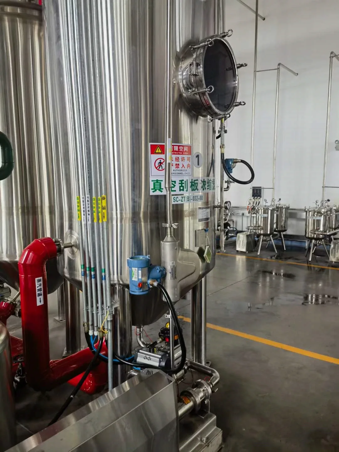
Specialty chemicals, Western Europe. A producer needed to meter an abrasive paste at 100 to 500 kg/h on a DN80 line, with viscosity around 7,000 cP at 40 C and minimum added pressure loss. At that viscosity the pipe Reynolds number sits deep in the laminar range, so every technology with a Reynolds number floor was ruled out. We proposed a DN50 straight-tube Coriolis mass flow meter with CE and ATEX documentation: direct mass reading, no Reynolds requirement, and a low-loss straight tube.
Fluid properties
The presets in the calculator use these values. Viscosity is the input that moves Re the most between fluids: from water at 20 C to a VG32 oil the kinematic viscosity rises by a factor of about 32, and at equal velocity and bore the Reynolds number falls by exactly that factor.
| Fluid | Density (kg/m³) | Dynamic viscosity (cP) | Kinematic viscosity (cSt) |
|---|---|---|---|
| Water, 20 C | 998.2 | 1.002 | 1.00 |
| Water, 60 C | 983.2 | 0.467 | 0.47 |
| Air, 20 C, 1 atm | 1.204 | 0.0181 | 15.0 |
| ISO VG32 hydraulic oil, 40 C | 860 (typical) | 27.5 | 32 (by ISO 3448 definition) |
Typical handbook values; properties shift with temperature, and oils especially so. Use Custom for your own data.
Worked example
A VG32 hydraulic oil return line, DN50 (50 mm bore), running 2 m³/h at 40 C. Is a DP element an option?
- Velocity: v = 4Q/(πD²) = 4 · (2/3600) / (π · 0.05²) = 0.283 m/s
- Reynolds number: Re = 860 · 0.283 · 0.05 / 0.0275 = about 442, laminar
- Minimum flow to reach the ISO 5167 orifice floor of Re = 5,000: 22.6 m³/h, more than eleven times the actual flow
The line will never see that flow, so no orifice sizing will bring this line into range. That conclusion took three numbers, and it is the calculation worth running before any DP element is quoted for a viscous fluid. Mode three of the calculator reproduces the 22.6 m³/h answer directly.
Related guides and tools
The Reynolds number this page computes feeds directly into the friction factor in our pipe pressure drop calculator, and the velocity it starts from can be checked against line-sizing practice in the pipe velocity calculator. If the Re result clears the floors above and you are sizing a DP element, the equation chain continues in our differential pressure flow calculation guide.
The selection logic behind these floors, technology by technology and with the worked minimum-flow math, is covered in our Reynolds number and flow meter selection guide.
For the shedding physics behind that vortex Reynolds limit, from automotive MAF sensors to process meters, see the Karman vortex air flow sensor guide.
FAQ
How is the Reynolds number calculated?
Multiply fluid density, velocity, and pipe inside diameter, then divide by the dynamic viscosity: Re = ρvD/μ. With kinematic viscosity, Re = vD/ν. From a flow rate, use Re = 4ρQ/(πDμ). The number is dimensionless, so the units just have to be consistent.
What if the Reynolds number is 4000?
Re = 4,000 sits at the top of the transitional band that starts near 2,300. The flow is on the edge of fully turbulent behavior and can still be intermittent. For design work, treat it as barely turbulent, and note that it is below the Re 5,000 floor of the standard orifice range and far below typical vortex meter guidance.
What are the two main formulas for calculating the Reynolds number?
The dynamic-viscosity form Re = ρvD/μ and the kinematic-viscosity form Re = vD/ν. They are the same equation, since ν = μ/ρ. Which one you use depends on how the fluid data is published: water and gas tables usually give both, oil grades are usually specified in centistokes, which is kinematic.
How to calculate Reynolds number from flow rate?
Convert flow to velocity with v = 4Q/(πD²), or use the combined form Re = 4ρQ/(πDμ) with Q in m³/s. In US units, Re = 3160 · Q · SG / (d · μ) with Q in GPM, d in inches, and μ in cP. The first calculator mode on this page does exactly this.
Request a quote
If your Reynolds number lands below the floor of the technology you had in mind, send us the fluid, viscosity, line size, and flow range. We will recommend a measurement principle that works at your real operating point and size it for the pipe you have. Tell us the application and we configure one unit, not a shelf part. Reach our application engineers or use the form below.
Written and technically reviewed by Wu Peng and the Instranova engineering team.