Flow Meters › Thermal Mass Flow Meters › Compressed Air Flow Meter
Compressed Air Flow Meter
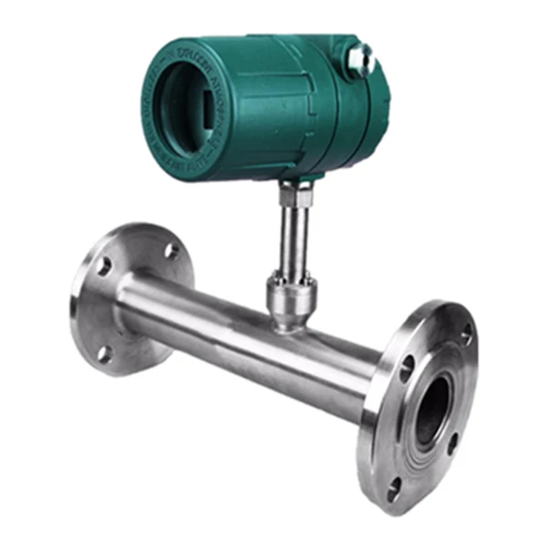
A compressed air flow meter built on the thermal mass principle reads the mass, or standard volume, of compressed air directly from the heat a warmed sensor loses to the passing air. Because it reads mass, it needs no separate temperature or pressure compensation, so it gives a true Nm3/h reading for energy monitoring, leak detection, and per-machine accounting.
- Principle: Thermal dispersion, direct gas mass flow
- No compensation: Reads mass; no T or P correction needed
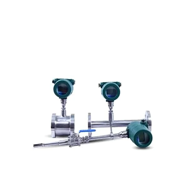
- Form: Inline DN10 to DN80, insertion DN80 to DN4000
- Velocity: 0.1 to 100 Nm/s, wide turndown
- Accuracy: +/-1.5% to 2.5%
- Output: 4-20 mA, pulse, RS485, HART
Overview
A compressed air flow meter measures how much air a plant actually uses. Built on the thermal mass principle, it reads the mass flow of compressed air directly, so the result is a true standard-volume reading in Nm3/h that does not drift as line pressure or temperature change. That makes it the standard choice for compressed-air energy monitoring, leak surveys, and charging air by line or machine.
The meter installs inline on branch lines from DN10 to DN80, or as an insertion probe on large headers, downstream of the dryer and receiver where the air is clean and dry. With a wide turndown it reads both the small overnight leakage flow and the full production demand. For a simple flow or no-flow signal rather than a rate, use a thermal flow switch instead.
Features
Everything here follows from one idea: read gas mass directly from heat loss, instead of reading volume and correcting it.
Direct mass, no compensation
It reads gas mass flow directly, so there is no separate temperature and pressure compensation to buy, wire, or maintain.
Very wide turndown
It reads from about 0.1 Nm/s up to 100 Nm/s, so it catches creeping flow and even gas leaks that other meters miss.
No moving parts
Nothing spins or wears, the pressure loss is negligible, and the insertion probe installs through a single tap.
Inline or insertion
An inline body suits DN10 to DN80; an insertion probe reaches DN80 to DN4000, for ducts and large gas mains.
Standard outputs and alarms
4-20 mA, pulse, RS485 Modbus, and HART, plus one or two alarm relays for high or low flow.
Wide gas range
Air, natural gas, coal gas, LPG, flare gas, hydrogen, CO2, nitrogen, and flue gas; most gases except acetylene.
Working principle
A thermal mass flow meter uses two elements in the gas: one measures the gas temperature, and one is heated a fixed amount above it. As gas flows past the heated element, it carries heat away. The mass of gas moving past sets how much heat is lost, so the power needed to hold the temperature difference, or the size of that difference, is a direct measure of mass flow. Gas density is already built into that heat transfer, which is why the meter reads mass without a separate pressure or temperature correction.
Because the reading comes from heat transfer rather than from a spinning rotor or a pressure drop, the meter has no moving parts, almost no pressure loss, and a very wide range. It does need a clean, dry gas at the sensor, since droplets or heavy dust change the heat transfer, so a filter and a drain are fitted where the gas is wet or dirty.
Technical specifications
| Parameter | Specification |
|---|---|
| Measurement principle | Thermal dispersion (calorimetric); heat carried from a warmed sensor is proportional to gas mass flow |
| Measured medium | Most gases except acetylene: air, natural gas, coal gas, LPG, flare gas, hydrogen, CO2, nitrogen, flue gas |
| Form and size | Inline DN10 to DN80; insertion DN80 to DN4000 |
| Velocity range | 0.1 to 100 Nm/s, wide turndown |
| Accuracy | +/-1.5% of reading for the pipeline (inline) type, +/-2.5% for the insertion type |
| Process temperature | Sensor -40 C to 220 C; transmitter -20 C to 45 C |
| Working pressure | Up to 1.6 MPa (higher on request) |
| Compensation | None needed; gas mass flow is read directly |
| Output | 4-20 mA (opto-isolated, max load 500 ohm), pulse, RS485, HART; 1 to 2 alarm relays |
| Response time | About 1 second |
| Power supply | Compact: 24 VDC or 220 VAC, up to 18 W; remote: 220 VAC, up to 19 W |
| Moving parts | None; negligible pressure loss |
| Wetted material | Stainless steel sensor and probe |
Calibration is gas-specific, so the meter is set for your gas. Send the gas, the line or duct size, the flow range, and the pressure and temperature and we size it.
Flow ranges by size
The pipeline (inline) body covers DN10 to DN300; the insertion probe carries the same measurement to DN4000. Flow ranges are in standard cubic metres per hour (Nm3/h):
| DN | Flow range (Nm3/h) | DN | Flow range (Nm3/h) |
|---|---|---|---|
| DN10 | 0.3-30 | DN80 | 18-1800 |
| DN15 | 0.6-60 | DN100 | 28-2800 |
| DN20 | 1.1-110 | DN125 | 44-4400 |
| DN25 | 1.8-180 | DN150 | 64-6400 |
| DN32 | 2.9-290 | DN200 | 130-13000 |
| DN40 | 4.5-450 | DN250 | 170-17000 |
| DN50 | 7-700 | DN300 | 254-25400 |
| DN65 | 12-1200 | to DN4000 | insertion type |
Pick the size so the normal flow sits in the upper part of the range. Consult us for sizes or ranges not listed.
Inline or insertion
The same measurement comes in two bodies, chosen by pipe size. An inline meter carries the sensor in its own flanged spool for small pipe, where it is easy to mount and gives a settled flow. An insertion meter puts the sensor on a probe that reaches into the pipe through one tap, which is the economical way to meter large mains and rectangular ducts, and it can be fitted on a live line.
| Form | Best for |
|---|---|
| Inline (flanged) | DN10 to DN80; small pipe, easy mounting, a settled flow profile |
| Insertion (probe) | DN80 to DN4000; large mains and ducts, single-tap and live install |
Applications
A compressed air flow meter turns air into a measured, costed utility:
- Plant and branch-line compressed-air consumption monitoring
- Leak surveys and overnight no-load baseline flow
- Energy audits and specific power, in kWh per Nm3
- Charging air by department, line, or machine
- Compressor and dryer performance and demand profiling
Application example
Challenge: A factory could not tell which of three production halls drove its rising compressed-air bill.
Solution: Thermal compressed air flow meters were fitted on each branch header, reading Nm3/h to the energy system.
Result: The team saw a large overnight no-load flow on one branch, traced it to leaks, and charged air use back to each hall by measured volume.
Related products
 Thermal Mass Flow Meter
The general thermal mass meter for natural gas, nitrogen, and other gases.
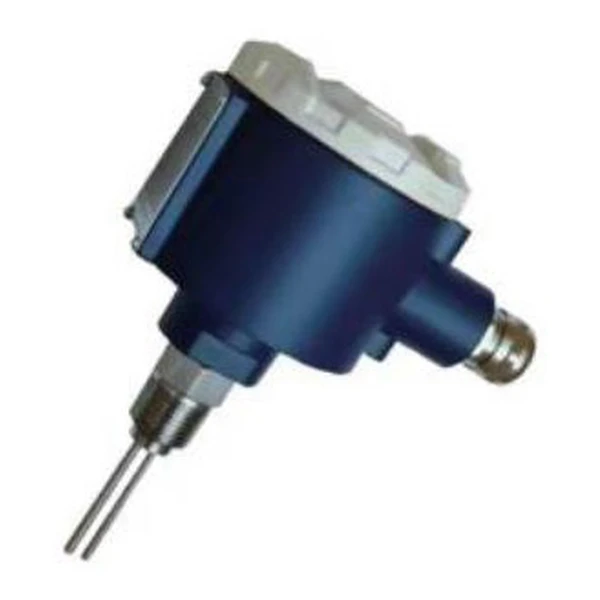 Thermal Flow Switch
Flow or no-flow detection for pump and line protection, no rate output.
FAQ
How do you measure compressed air flow?
The usual method is a thermal mass flow meter. A heated sensor in the air stream loses heat in proportion to the mass of air passing, so the meter reads mass, or standard volume in Nm3/h, directly, without separate temperature or pressure correction.
Why use a thermal mass meter for compressed air?
Compressed air is billed and audited by mass or standard volume, and thermal mass reads that directly with a wide turndown, so it captures both small leakage flows and full demand. It has no moving parts and adds almost no pressure drop.
Where should a compressed air flow meter be installed?
Install it downstream of the dryer and receiver, where the air is clean and dry, on a straight run of pipe. Allow several diameters of straight pipe upstream and a couple downstream so the flow profile is stable.
Flow meter or flow switch?
Use a compressed air flow meter when you need the actual rate or a total for energy and leak work. Use a thermal flow switch when you only need a flow or no-flow signal, for example to confirm air is moving.
Request a quote
Send us the gas, the line or duct size, the flow range, and the pressure and temperature, and we size the thermal mass flow meter and calibrate it for your gas.