Flow Meters › Seal Water Flow Meter
Seal Water Flow Meter
A seal water flow meter measures the small, continuous stream of clean water fed to a mechanical seal or a packed gland. The stream is small and the line is usually 3/8 in. or DN15. Losing it does not produce a bad reading. It produces a wrecked seal face, often within minutes of the faces running dry.
Small flow with a large consequence is what separates this choice from every other water line in the plant. This page covers industrial seal flush and gland service water on pumps: API Plan 32 external injection, Plan 62 quench, and water to packed glands. It is not about the flush valve seals sold for plumbing fixtures. It is also not about diaphragm seal pressure transmitters, which use the word seal in another sense.
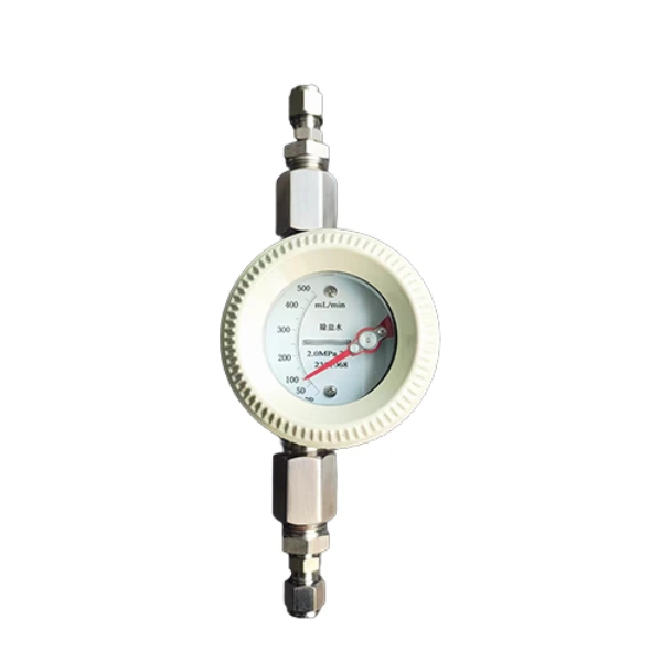 Low Flow Rotameter
DN6 to DN25 with an integral needle valve, water from 0.1 to 3000 L/h. The usual local indicator on a single seal flush line.
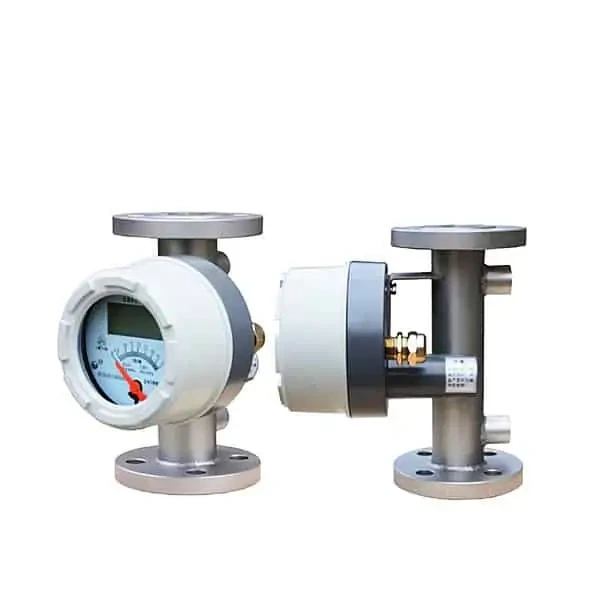 Metal Tube Rotameter
DN15 to DN150, water 2.5 to 150000 L/h, magnetic dial with optional 4-20 mA and HART. For gland water headers feeding several pumps.
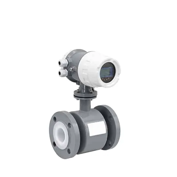 Magnetic Flow Meter
Full bore from DN6 up, no moving parts and no added pressure drop, ±0.5% of reading. For a signal to the control system when the water conducts well enough.
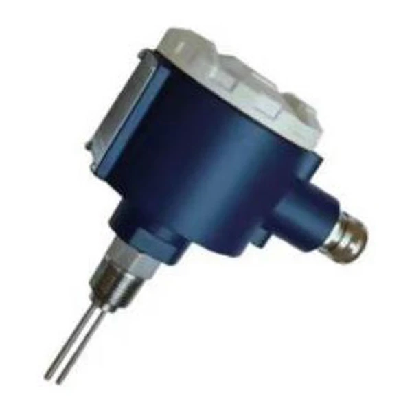 Thermal Flow Switch
Relay contact at a set velocity, G1/2 connection, process water to 260 deg C. For the loss of flush alarm or the pump interlock.
Seal water service
Flush water does three things at the seal faces. It carries away the heat the faces generate, it keeps a liquid film between them, and it holds process solids out of the seal chamber.
On an API Plan 32 arrangement the water comes from an external source. It is injected into the seal chamber against a close clearance throat bushing, so the bushing holds the pressure and limits how much process fluid works its way back in. Plan 62 puts a low pressure stream on the atmospheric side of the seal instead. A packed pump takes gland service water through the lantern ring.
Position decides what the reading means. The meter belongs downstream of the strainer and the control valve, and upstream of the seal. Then it reads what the seal receives rather than what the header offers. One distributor guide to the plan choices ranks the flow meter above the control valve and the pressure gauge, because a positive flow into the pump is the one thing an operator needs to confirm.
The pressure margin over seal chamber pressure is published three different ways: 10 to 15 psi, 15 to 20 psi, and at least 10 psi rising toward 25 psi. In bar, the published margins run 0.69 to 1.72. None of those sources ties the figure to a standard clause.
How much flush flow
Published guidance on pump seal water flow rate does not converge. Four rules circulate widely, and on the same 2 in. seal they land far apart.
| Rule | As published | On a 2 in. seal | Where it comes from |
|---|---|---|---|
| Absolute minimum | 1/8 gpm | 0.125 gpm (0.47 L/min) | Independent seal reference |
| Field typical | 0.25 to 0.50 gpm | 0.95 to 1.89 L/min | Distributor field practice |
| Heat balance | Flow that holds the temperature rise to 15 deg F in water | 0.4 gpm (1.51 L/min) for a balanced seal at 3600 rpm, 250 psig | Trade journal worked example |
| Rule of thumb | 1 gpm per inch of seal size | 2 gpm (7.57 L/min) | Repeated across several sources |
The top and bottom of that table differ by 16 to 1 for one seal, an absolute floor at one end and a rule of thumb at the other. The allowable temperature rise behind the heat balance line is fluid dependent: 15 deg F for water, 5 deg F for light hydrocarbons, 30 deg F for oils. The same seal on propane therefore needs several times the water it needs on water.
A separate starting point used for seal isolation sets about 15 fps (4.57 m/s) through the throat bushing. That is a velocity target rather than a flow rate, and it lands somewhere different again.
The rule of thumb needs two checks of its own. Across the shaft sizes API 682 covers, 20 mm to 110 mm, it asks 0.75 gpm at the small end and 4.3 gpm at the large end. The rule alone therefore spans 5.7 to 1 before the other rules are considered.
The metric form is the second check. It is often reprinted as 0.16 L/min per mm. Converted properly, 1 gpm per inch is 0.149 L/min per mm, so the reprinted figure runs about 7 percent high. Take the rate the seal vendor states for the seal you have, then use these rules to confirm it is bracketed sensibly.
Instrument options
Which of the four you need follows from what the reading is for: a set and forget local indication, a header serving several pumps, a signal the control system can log, or a contact that trips.
| Instrument | Water range | Accuracy | Output | Where it fits |
|---|---|---|---|---|
| Low flow rotameter | 0.1 to 3000 L/h, DN6 to DN25 | Grade 2.5 or 4.0 of full scale | Dial, optional 4-20 mA, limit alarms | Single seal flush line with a needle valve to set the rate |
| Metal tube rotameter | 2.5 to 150000 L/h, DN15 to DN150 | Grade 1.5 or 2.5 of full scale | Dial, optional 4-20 mA with HART | Gland water header, higher pressure, no glass tube |
| Magnetic flow meter | DN6 and up, full bore | ±0.5% of reading | 4-20 mA, pulse, RS485 | Conductive water, logged flow, nothing to foul or wear |
| Thermal flow switch | Velocity set point, G1/2 or G3/4 | Set point repeatability, not a rate | Relay 30 VDC / 5 A or 250 VAC / 4 A | Alarm and interlock alongside an indicator |
A variable area flow meter remains the default on a single line. The needle valve that sets the rate and the scale that shows it sit in one body, with no power and no wiring. It also reads liquids that do not conduct, which matters once the water source is treated. The magnetic meter is the choice once the reading has to leave the pump skid.
Sizing the scale
Scale selection decides whether the meter can show the number you need, and the vendor literature skips it. Seal water meters are sold in narrow ranges, and several of the ranges on offer are scaled for the field typical world rather than the rule of thumb world. One common build spans 2 to 50 USGPH, which is 0.033 to 0.833 gpm.
Apply 1 gpm per inch to a 2 in. seal and you need 2 gpm. That build cannot show the number at all: the float sits against the stop and the operator has nothing to set against. The same vendors do list higher ranges, so the error is in which build gets ordered rather than in what is available.
The second trap is the accuracy statement. Variable area meters are graded against full scale, not against reading. The error in engineering units stays fixed while the percentage of what you are reading grows as the flow falls. Grade 2.5 on a 0 to 2 gpm scale is ±0.05 gpm anywhere on the dial.
| Flush rate on a 0 to 2 gpm scale | Grade 2.5 error | Same error as percent of reading |
|---|---|---|
| 2 gpm, rule of thumb on a 2 in. seal | ±0.05 gpm | ±2.5% |
| 0.4 gpm, heat balance minimum | ±0.05 gpm | ±12.5% |
| 0.125 gpm, absolute minimum | ±0.05 gpm | ±40% |
Turndown puts a floor under the same problem. At 10:1 the bottom of a 0 to 2 gpm scale is 0.2 gpm. Below that the float position shows that water is moving rather than how much. Size the scale so the normal flush rate sits in its upper half, and let the alarm point carry the low flow case.
The water arithmetic is worth doing once. A seal flushed continuously at 2 gpm passes 1,051,200 gallons, or 3,979 m³, in a year. The same seal at 0.5 gpm passes 262,800 gallons, or 995 m³. The difference of 2,984 m³ per seal per year is why plants with hundreds of sealed pumps meter this water rather than leaving a valve cracked open.
Water quality limits
Seal water is described as clean water, which hides two properties that decide the instrument. The first is conductivity. A magnetic flow meter needs a conducting liquid, and the practical floor is 5 µS/cm. Municipal water usually sits well above that.
Water drawn from a demineralizer or a condensate polishing loop does not. Ultrapure water at 25 deg C has a conductivity of 0.055 µS/cm, about 91 times lower than the magnetic meter floor, and treated water short of that limit can still fall under it. Measure the conductivity at the tap before a magnetic meter is specified, or choose a technology that reads the flow regardless of conductivity.
The second property is what the water leaves behind. Hardness, iron, and fine solids build up in small bore and on float guides. Scale on the tube bore shrinks the annulus, so the float rides higher for the same flow and the meter reads high; deposits on the float itself do the opposite. The high side is the one to watch, because it shows flow the seal is not getting.
A strainer upstream is standard practice, and the meter reads only what the strainer passes. Meters that can be cleaned without breaking into the line are worth the premium in hard water. Choose the wetted parts against the water chemistry rather than against the process fluid the pump handles, a distinction covered in the guide to wetted parts and wetted materials.
Alarm and interlock
A seal water flow meter for mechanical seals reports the rate. It does not stop the pump when that rate collapses, and the flush often runs unattended for long stretches. A seal water flow switch supplies the contact an alarm or an interlock needs, either as a limit contact on the rotameter or as a separate switch in the same line.
Two instruments in the line also turn the flush into a diagnostic. Flow that rises while pressure falls points toward a leak path on the inboard face. Flow that falls while pressure rises points toward a blocked strainer or filter. A flow meter alone cannot separate those two, which is the argument for keeping the pressure gauge.
Set the low flow alarm below the normal flush rate and above the minimum the seal vendor states. Record the set point where the next person will find it. That question returns for gland seal water flow rate on every packed pump in the same house.
What API 682 covers
API Standard 682, fourth edition, is dated May 2014 and runs to 256 pages. It covers shaft sealing systems for centrifugal and rotary pumps with shaft diameters from 20 mm (0.75 in.) to 110 mm (4.3 in.). Clause 9 is devoted to instrumentation and includes a sub-clause on flow instruments.
Annex G is normative and holds the standard piping plans, with the Plan 32 figure among them. Annex F is informative and presents typical required flush flow for Arrangement 3 CW seals as charts. Those charts run from a pumped fluid temperature of 54 deg C without heat soak up to 176, 260 and 371 deg C with heat soak considered.
That structure answers a question this page cannot dodge. Flush flow sizing sits in an informative annex as a temperature dependent curve, while the plan arrangement and its instrument symbols sit in a normative one. The 1 gpm per inch rule and the 15 fps throat bushing target are industry practice.
None of the published sources reviewed for this page traces either figure to a clause of the standard, and the standard is a paid document that cannot be reproduced here. Treat those numbers as starting points and treat the seal vendor’s stated rate as the specification. We supply flow instruments for seal water and gland water lines. We do not supply API 682 seal support systems and we do not certify a piping plan against the standard.
Applications
Seal water metering concentrates in the industries that pump abrasive or fibrous liquids, where the flush exists to keep solids out of the seal chamber rather than only to cool it.
- Pulp and paper: stock pumps and gland service water, where the water bill and the seal bill are both large enough to justify metering every pump.
- Mining and mineral processing: slurry pump gland water, in the same plants that meter the slurry itself.
- Municipal wastewater: raw sewage and sludge pumps, often feeding many seals from one header, covered further in the water and wastewater instrumentation pages.
- Chemical processing: Plan 32 injection where the process fluid would crystallize or polymerize between the faces.
- Power generation: boiler feed and condensate service pumps, which is where the conductivity limit above tends to bite.
Application note
Our case records cover 330 projects and none of them is a seal water line. This instrument is normally bought with the pump or the seal rather than as a separate instrument order, so the parameters reach us second hand through the pump package. Four numbers settle the selection: the flush rate the seal vendor states, the seal chamber pressure, the water temperature, and the line size and connection. With those in hand the scale, the wetted materials and the alarm point all follow.
FAQ
What is the recommended flow rate for mechanical seal flushing?
There is no single recommended figure: the published values span 16 to 1 on the same 2 in. seal, from an absolute minimum of 1/8 gpm to the 2 gpm that the common rule of thumb gives. That rule, 1 gpm per inch of seal size, is the most widely repeated. Field practice often runs far lower, around 0.25 to 0.50 gpm. Use the rate the seal vendor specifies for the seal in front of you and use the rules to check it.
What is flushing in a mechanical seal?
Flushing is a deliberate stream of liquid brought to the seal faces. It carries off the heat they generate, keeps a liquid film between them, and excludes solids from the seal chamber. The liquid can be taken from the pump discharge and returned to the seal, or injected from a clean external source. The external arrangement is what API Plan 32 describes, and it is the one that normally carries a flow meter.
What is the acceptable leakage rate for a mechanical seal?
That is a property of the seal, set by its type and by the standard the pump was bought to, and a flow meter on the flush line does not measure it. What the flush instrument can show is a change. Flush flow that climbs while flush pressure falls suggests a leak path has opened on the inboard face. Ask the seal vendor for the leakage limit that applies to the arrangement supplied.
What is the purpose of a water flow meter?
On a seal water line the purpose is narrower than on a process line. It proves that a positive flow reaches the seal, lets an operator set that flow to a stated rate with a valve, and gives a number that can be trended or alarmed. Billing accuracy is not the point. A repeatable reading at the rate the seal needs is.
Request a quote
Tell us the flush rate the seal vendor specifies, the seal chamber pressure and water temperature, the line size and connection, and whether you need a local dial, a 4-20 mA signal, or a contact for the pump interlock. Say if the water comes from a treated or demineralized header, because that decides whether a magnetic meter is open to you at all. We size the scale so the normal rate sits in the upper half of the range and set the alarm point below it.