By Wu Peng, Senior Process Instrumentation Engineer · Last reviewed July 29, 2026
A 2-wire RTD adds the resistance of both lead wires straight into the temperature reading. A 3-wire RTD lets the instrument measure the lead loop separately and subtract it. A 4-wire RTD removes lead resistance from the measurement completely. On a Pt100, every ohm of uncompensated lead resistance reads as about 2.6 °C of false temperature, so the wire count decides how much error the cable itself adds.
The numbers get large quickly. Run 50 m of 22 AWG cable to a 2-wire Pt100 and the copper alone reads as 13.8 °C. This guide gives you the wiring diagram for each connection, an error table by wire gauge and cable length, the IEC 60751 color code, the rules for mixing wire counts and instrument inputs, and a three step multimeter check.
Contents
- Why lead wires matter
- 2-wire connection
- 3-wire connection
- 4-wire connection
- Error by cable length
- Wire color codes
- Mixing configurations
- Multimeter checks
- The transmitter alternative
- Choosing a configuration
- FAQ
Why lead wires matter
An RTD is a resistance measurement. A Pt100 element sits at 100.00 ohms at 0 °C and changes by roughly 0.385 ohms per °C. The instrument cannot tell element ohms from cable ohms, so any lead resistance it fails to cancel is converted to temperature at the same rate. Divide 1 by 0.385 and you get the number worth memorizing: 1 ohm of uncompensated lead resistance reads as about 2.6 °C.
That error is large compared with what the sensor itself is allowed. IEC 60751 gives a Class B element a tolerance of ±0.80 °C at 100 °C and a Class A element ±0.35 °C.
Just 10 m of 22 AWG cable on a 2-wire hookup adds 2.75 °C, which is 3.4 times the entire Class B budget. Paying for a tight tolerance class and then losing it in the cable is a common way an RTD installation goes wrong. How that tolerance interacts with repeatability is covered in our guide to accuracy vs precision in measurement.
A thermocouple does not share this problem in the same form because it produces a voltage rather than a resistance, but it trades that for cold junction and extension wire issues. See the thermocouple page for where each sensor fits, and the thermocouple types chart for the letter types themselves.
2-wire connection
In a 2-wire hookup the instrument pushes a small measuring current through the element and reads the voltage across the same two terminals. What it computes is the element resistance plus both lead wires in series. There is no way to separate the three, so the full cable loop appears as extra temperature.
A 2-wire connection is acceptable when the leads are too short to matter. A sensor plugged into a local indicator through 1 m of 22 AWG cable adds about 0.1 ohm, well under 0.3 °C. It also becomes workable with a Pt1000 element, because the element changes about 3.85 ohms per °C and the same cable produces one tenth of the error. For anything on a cable tray, treat 2-wire as a rough alarm input, not a measurement.
3-wire connection
The 3-wire connection is the industrial default. Two leads land on one end of the element and a single lead lands on the other. The instrument can now drive current through one pair and measure the resistance of the lead loop on its own, then subtract that loop from the total.
Classic controllers did this with a Wheatstone bridge; modern inputs do the same arithmetic with a constant current source and an ADC. The principle is identical: the third wire gives the instrument a sample of the cable so it can cancel it.
The subtraction rests on one assumption: all three conductors have equal resistance. Use the same gauge, the same length, and route them in the same cable so they sit at the same temperature.
What remains after compensation is only the mismatch between conductors. A 0.1 ohm mismatch leaves 0.26 °C of error. On a 100 m run of 22 AWG, each conductor is 5.3 ohms, so even a 5 percent mismatch leaves about 0.7 °C. That is the practical accuracy floor of a long 3-wire run, and the reason the instrument input must be a true 3-wire type for the cancellation to happen at all.
4-wire connection
A 4-wire connection separates the current path from the voltage measurement. The measuring current enters and returns through the outer pair. The inner pair connects to a high impedance voltage input, and since almost no current flows in a high impedance branch, those two leads drop almost no voltage.
The instrument sees the voltage across the element alone, and lead resistance drops out of the math entirely. Electrical engineers call this Kelvin sensing.
The same mechanism also cancels contact resistance at terminal blocks and connectors, which 3-wire compensation cannot do. That is why calibration laboratories, Class A and Class AA sensors, and custody measurements are wired 4-wire as a rule. The only costs are one more conductor and an input channel that supports it.
Error by cable length
The table below is the 2-wire error you would add to a Pt100 reading, computed from standard resistance values for solid annealed copper at 20 °C. Loop resistance counts both conductors.
| Wire gauge | Ohm per km, one conductor | 10 m run | 30 m run | 100 m run |
|---|---|---|---|---|
| 16 AWG | 13.2 | 0.26 ohm, 0.7 °C | 0.79 ohm, 2.1 °C | 2.63 ohm, 6.8 °C |
| 18 AWG | 20.9 | 0.42 ohm, 1.1 °C | 1.26 ohm, 3.3 °C | 4.19 ohm, 10.9 °C |
| 20 AWG | 33.3 | 0.67 ohm, 1.7 °C | 2.00 ohm, 5.2 °C | 6.66 ohm, 17.3 °C |
| 22 AWG | 53.0 | 1.06 ohm, 2.8 °C | 3.18 ohm, 8.3 °C | 10.6 ohm, 27.5 °C |
| 24 AWG | 84.2 | 1.68 ohm, 4.4 °C | 5.05 ohm, 13.1 °C | 16.8 ohm, 43.7 °C |
Loop resistance = length x ohm/m x 2 conductors. Temperature error = loop resistance / 0.3851 ohm per °C for Pt100. Copper resistance rises about 0.4 percent per °C, so hot cable trays add a little more.
Follow one run through the wiring choices. Take 50 m of 22 AWG: the loop is 5.30 ohms. Wired 2-wire, that is 13.8 °C of error.
Wired 3-wire with the leads matched within 5 percent, the residue is 0.27 ohm, about 0.7 °C. Wired 4-wire, the cable drops out and the error is set by the element class alone. A Pt1000 element divides every figure in the table by ten, which is why 2-wire Pt1000 sensors are common in building automation.
Published figures for cable error vary widely from source to source. Skip the shortcuts and compute your own: take the ohm per km value for your gauge, multiply by length and by two, and divide by 0.385.
Wire color codes
IEC 60751 sets the lead colors for a single Pt100 circuit: red and white. A 2-wire sensor has one red and one white lead. A 3-wire sensor has two red and one white. A 4-wire sensor has two red and two white.
The rule that matters on the bench: leads of the same color connect to the same end of the element. The two reds of a 3-wire sensor are the current pair; the white is the opposite end. Duplex assemblies carry a second element with its own color pair, and some manufacturers still use house schemes, so confirm against the sensor datasheet before landing wires.
Unlike a thermocouple, an RTD needs no special extension alloy. Ordinary copper instrument cable extends the circuit without creating junction errors, which keeps long runs cheap. Use a shielded, twisted cable, ground the shield at the instrument end only, and keep all conductors of one sensor in the same cable so they share gauge, length, and temperature.
Mixing configurations
Sensors and inputs rarely arrive matched, and most combinations can be adapted at the terminals.
| Combination | What to do |
|---|---|
| 4-wire sensor, 3-wire input | Land one red, the second red, and one white. Insulate and tape back the spare white. You get full 3-wire performance. |
| 4-wire sensor, 2-wire input | Use one red and one white; insulate the spares. All the 2-wire cable error applies. |
| 3-wire sensor, 2-wire input | Use one red and the white; insulate the spare red. Cable error is uncompensated. |
| 2-wire sensor, 3-wire input | Add a jumper wire from one terminal at the sensor head and run three conductors back. Only the short pigtail inside the head stays uncompensated. |
One wiring mistake defeats the whole scheme: jumpering the two red terminals together at the instrument end instead of running both conductors back to the sensor. The input then measures a zero length loop, subtracts nothing, and the display carries the full cable error with no warning. If a drawing shows two red wires joined, that junction belongs at the element, not at the panel.
Multimeter checks
Three resistance readings identify the leads and the health of a 3-wire sensor. First, measure between the two same colored leads: you should see only the lead resistance, typically 0 to 2 ohms with the meter at the head.
Second, measure from either of those to the odd colored lead: you should see the element plus leads, about 108 to 110 ohms for a Pt100 at room temperature, since the element itself sits at 107.8 ohms at 20 °C. Third, measure from any lead to the probe sheath: a healthy sensor reads many megohms.
An open circuit reading on the element pair means a broken element or lead, which a transmitter reports by driving the output to its configured failure level. Two pair readings that differ by more than the expected lead resistance mean you have misidentified the pairs; regroup by color and repeat. Readings that drift while you flex the cable point to a damaged conductor or a wet junction box.
The transmitter alternative
Past a certain cable length the better answer is to stop transporting ohms altogether. A head mounted temperature transmitter screws into the sensor connection head, measures the element right at the source with a proper 3-wire or 4-wire front end, and sends 4-20 mA back to the panel.
A current signal does not change with cable resistance, so the run back to the control system can be hundreds of meters of ordinary two core cable without adding a single degree of error. It also isolates the measurement from ground loops and noise that raw element wiring picks up.
Application example
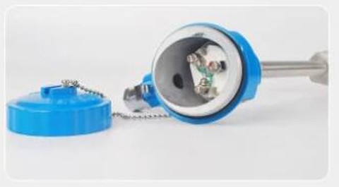
Industrial plant, Pakistan. The customer asked for process temperature measurement over a 0 to 250 °C span with a 1/2 inch NPT process connection and a 3 inch probe, powered from 24 VDC. We quoted an RTD assembly with the transmitter fitted in the connection head, delivering 4-20 mA on the loop, so the panel receives a current signal that stays accurate regardless of how far the cable runs.
Choosing a configuration
| Situation | Wiring to specify |
|---|---|
| Leads under about 1 m, local display | 2-wire is fine; consider Pt1000 if the run may grow |
| General industrial run to a PLC or controller | 3-wire with matched conductors in one shielded cable |
| Class A or AA element, calibration, custody | 4-wire into a true 4-wire input |
| Run past 100 m, or electrically noisy plant | Head mounted transmitter, 4-20 mA back to the panel |
Our RTD temperature sensors ship in 2, 3 or 4-wire form to order, and the matching head mounted or field mounted transmitters are on the temperature transmitter page. The rest of the measurement chain, from thermowells to indicators, is grouped under temperature instruments. If you are still deciding how tight a tolerance you need, our note on full scale vs reading accuracy shows how to read the spec sheet before you pay for precision the wiring would throw away.
Choosing between the sensor families in the first place is a separate question; our RTD vs thermocouple comparison covers it.
FAQ
Why does an RTD have 3 wires?
The third wire lets the instrument measure the resistance of the lead loop separately and subtract it from the total reading. Without it, the cable resistance adds directly to the element resistance and reads as extra temperature, about 2.6 °C per ohm on a Pt100.
How does a 3 wire RTD work?
Two leads connect to one end of the element and one lead to the other. The instrument drives its measuring current through the element, separately measures the loop formed by the two same side leads, and subtracts that loop resistance. The result is the element resistance alone, provided all three conductors match.
How do I connect a 4 wire RTD to a 3 wire instrument?
Land both leads from one end of the element plus one lead from the other end, and insulate the spare. The input compensates exactly as it would with a native 3-wire sensor, so nothing is lost except the contact resistance immunity of true 4-wire measurement.
What is the difference between 2 wire, 3 wire and 4 wire RTDs?
The element is identical; only the lead count changes. Two wires give no lead compensation, three wires cancel lead resistance as long as the conductors match, and four wires eliminate lead and contact resistance completely by separating the current and voltage paths.
Request a quote
Tell us the application, the cable run, and the input type on your controller, and we will configure the RTD with the right wire count, or fit a head mounted transmitter so the cable length stops mattering. Reach our application engineers or use the form below.
Written and technically reviewed by Wu Peng and the Instranova engineering team.