By Wu Peng, Senior Process Instrumentation Engineer · Last reviewed September 16, 2026
A thermocouple is a temperature sensor made from two wires of different metals joined at one end. When the joined end sits at a different temperature than the open end, the pair produces a small voltage measured in millivolts. An instrument converts that voltage into a temperature reading.
The effect was described by Thomas Seebeck in 1821. It needs no power at the sensing tip, survives vibration, and covers service from cryogenic plants to furnaces above 1,600 °C with the right wire pair.
This guide answers what is a thermocouple in practical plant terms. It then takes the follow-up question, how does a thermocouple work once it is wired through terminals, extension cable and an input card.
The physics matters here: the classic wiring mistakes, and the reason a reading can drift years after installation, both come from details that shopping listings skip. One distinction up front: the thermocouple inside a gas water heater or furnace pilot is a real thermocouple. It plays a different role than a process sensor, though, and this guide covers both meanings so you land on the right one.
Contents
- Definition and parts
- The Seebeck effect
- Output by type
- Cold junction compensation
- Wiring and terminals
- Junction styles
- Two thermocouple worlds
- Thermocouple or RTD
- Specifying a probe
- FAQ
Definition and parts
Strip a thermocouple to its essentials and there are only four pieces: two dissimilar wires, one welded junction, and one readout instrument. Two conductors of different alloys run side by side. At the process end they are welded together into the measuring junction, often called the hot junction.
At the other end the wires terminate at the reference junction, historically called the cold junction. It is a location more than a component, sitting wherever the thermocouple alloys give way to copper: a terminal block, a connector, or the input of an instrument. The fourth piece is the voltmeter, transmitter or input card that reads the millivolt signal.
An industrial probe wraps those essentials in mechanical protection. The wire pair sits inside ceramic insulators or compacted mineral-insulated (MI) cable, and a metal sheath keeps the process out. A connection head on top gives the extension cable a place to land.
Many assemblies then slide into a thermowell so the sensor can be pulled without opening the line. The sensing element itself costs little; the sheath, fittings and head are the parts a spec sheet should pin down. Our thermocouple assemblies page shows how those pieces combine into an orderable sensor.
The Seebeck effect
Any metal wire with a temperature difference between its two ends develops a tiny internal voltage. That is the Seebeck effect. The size of the voltage per degree, the Seebeck coefficient, differs from alloy to alloy.
Join two different alloys at one end and the two internal voltages no longer cancel; the leftover appears across the open ends as a measurable signal. For the common Type K pair the net output averages about 41 µV per °C, so a 100 °C span produces only about 4 mV.
One point separates a correct explanation from a merely convenient one: the voltage is not generated at the junction. It develops along every length of wire that passes through a temperature gradient, from the tip all the way back to the reference end. The junction merely closes the circuit.
This is more than trivia. If a section of wire in the gradient zone becomes chemically altered by years of heat, its local Seebeck coefficient changes. The reading drifts even though the junction itself is intact. That is why a used thermocouple can pass a continuity test and still read wrong, and why moving an aged probe deeper into a furnace can shift its indication.
Output by type
Each standardized wire pair carries a letter, and each letter comes with its own sensitivity. The table below shows the average output between 0 and 100 °C, calculated from the standard reference tables; sensitivity changes with temperature, so treat these as comparison values, not constants.
| Type | Average output, 0–100 °C | Group |
|---|---|---|
| E | 63.2 µV/°C | Base metal |
| J | 52.7 µV/°C | Base metal |
| T | 42.8 µV/°C | Base metal |
| K | 41.0 µV/°C | Base metal |
| N | 27.7 µV/°C | Base metal |
| R | 6.5 µV/°C | Noble metal |
| S | 6.5 µV/°C | Noble metal |
| B | 0.3 µV/°C | Noble metal |
Derived from the ITS-90 reference tables: EMF at 100 °C divided by 100. Type B output is negligible near ambient, which is why its reference junction needs no compensation in practice.
The spread explains a lot of selection behavior. Type E gives the strongest signal, so it turns up in cryogenic and low-temperature work where every microvolt counts. The platinum pairs R, S and B produce a signal six times weaker than K yet run far hotter, which is why they pair with careful wiring and quality input electronics.
Type K sits in the middle: a healthy signal, a wide range and low wire cost, which made it the industry default. Ranges, tolerance classes and color codes for all eight letters are covered in our thermocouple types guide, and the K-specific detail lives in the Type K thermocouple guide.
Cold junction compensation
A thermocouple never measures temperature directly. It measures the difference between the measuring junction and the reference junction. The reference tables assume the reference end sits at exactly 0 °C, the old ice-bath convention.
Real terminals sit in a control room or a field enclosure at whatever temperature the day brings, so the instrument must correct for it. That correction is cold junction compensation, or CJC.
The arithmetic shows why it is not optional. A Type K junction at 100 °C produces 4.096 mV against a 0 °C reference. If the terminals sit at 25 °C, the wires only deliver the difference:
4.096 mV − 1.000 mV = 3.096 mV
An instrument without CJC looks up 3.096 mV in the table and reports roughly 76 °C. The error, 24 °C, is almost exactly the reference-junction temperature. A modern transmitter or input card measures its own terminal temperature with a small built-in sensor, adds the equivalent millivolts back, and then converts. When a reading is wrong by something close to room temperature, a CJC fault or misconfiguration is the first suspect.
Wiring and terminals
A fair question stops many first-time users. The signal path runs through brass terminals, copper test leads and tin-plated connectors, all made of metals that are neither of the thermocouple alloys.
The law of intermediate metals answers it. A third metal inserted into the circuit contributes no error, provided both of its ends sit at the same temperature. A terminal block in a uniform-temperature enclosure is electrically invisible. The rule only breaks when a temperature difference spans the foreign metal, which is exactly what happens when plain copper cable is used to cover a long run.
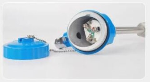
Run plain copper from the connection head to the panel and the reference junction silently relocates to the hot connection head, where no CJC sensor lives. The cure is matched wire: extension or compensating cable with the same thermoelectric behavior as the sensor pair, carried all the way to the compensated terminals.
Polarity discipline matters just as much. Swap the two extension conductors at the head and the mistake creates two opposing junctions. The reading then shifts by roughly twice the temperature difference between head and panel. A head at 80 °C against a panel at 25 °C can put the indication about 110 °C off.
Wire grades, color codes and the extension-versus-compensating distinction are covered in the Type K guide.
Junction styles
Sheathed probes are built with the junction in one of three styles, and the choice trades speed against protection. Speed is quoted as a time constant: the time to reach 63.2 percent of a temperature step, with about five time constants needed to read essentially all of it.
| Junction | Construction | Trade-off |
|---|---|---|
| Exposed | Welded bead protrudes from the sheath into the medium | Fastest response; no protection, dry non-corrosive gas service only |
| Grounded | Junction welded to the inside of the sheath tip | Good speed with full sheath protection; sheath connects the circuit to plant ground, so ground loops are possible |
| Ungrounded | Junction insulated from the sheath by compacted MgO | Slowest of the three but electrically isolated; the default for anything wired to shared or sensitive inputs |
Response also scales with mass: a thinner sheath answers a step change sooner, at the cost of ruggedness. Where milliseconds matter, an exposed fine-wire bead is the tool.
Plunge-test seconds by sheath diameter, the ground-loop arithmetic and the insulation checks behind this table are covered in our grounded vs ungrounded junction guide.
Application example
Industrial plant, India. An inquiry called for Type T thermocouples with a beaded measuring junction, the exposed style above, chosen where fast response on a modest temperature range matters more than mechanical protection. We proposed beaded-junction Type T elements, with wire gauge and the remaining construction details to be confirmed against the installation before quoting a final build.
Two thermocouple worlds
Search results mix two products that share a name. The industrial thermocouple measures temperature and hands a signal to a control system.
The pilot thermocouple in a gas water heater, furnace or fireplace is a safety device. Its tip sits in the pilot flame. The output, on the order of 25 to 30 mV from a healthy unit, directly energizes the coil of the gas safety valve. Flame out means voltage gone, and the valve springs shut.
No table lookup, no temperature display; the millivolts are used as muscle rather than as information. Some appliances stack many junctions in series as a thermopile to drive the valve at a few hundred millivolts; how that stack differs from a single junction is compared in our thermopile vs thermocouple guide.
The physics is identical, which is why both carry the same name, but the products are not interchangeable and the buying paths are separate. Appliance pilot parts come from HVAC suppliers as standardized replacement items. Everything else on this page, and everything we supply, belongs to the measurement world.
Thermocouple or RTD
The other sensor on the shortlist is the RTD, a platinum resistance element. The short version: an RTD is the accuracy and stability choice within roughly −200 to 600 °C, while a thermocouple wins on upper range, tip robustness, response speed and price per point. Above the RTD ceiling the decision makes itself. Below it, the trade is real and worth ten minutes with our RTD vs thermocouple comparison, or the RTD sensor page if resistance measurement already fits the application.
Specifying a probe
An orderable thermocouple is a short list of decisions: the type letter for range and environment, the junction style for speed versus isolation, and sheath material and diameter. Add immersion length, a thermowell where the line must stay closed, and the head.
The last decision is electrical: run matched extension cable to the control system, or mount a temperature transmitter in the head so ordinary copper carries a 4-20 mA signal instead of millivolts. Over long distances and through noisy areas, the transmitter route usually costs less than the special cable it replaces.
Which lead is positive depends on the code the cable was made to, and the thermocouple color code guide lists both current standards along with the withdrawn ones.
When a sensor already in service starts reading wrongly, the bench and loop checks that separate a broken element from wiring or instrument trouble are set out in how to test a thermocouple.
FAQ
Does a thermocouple make electricity?
Yes, in tiny amounts. A measuring thermocouple generates millivolts, useful as a signal, not as power. Pilot thermocouples on gas appliances use that self-generated voltage, around 25 to 30 mV, to hold a safety valve open, and thermopiles stack junctions to reach a few hundred millivolts.
How does a thermocouple read?
The instrument reads the millivolt difference between the measuring junction and its own terminals. It measures the terminal temperature with a built-in sensor, adds the equivalent voltage back, and converts the total to temperature through the reference table for that thermocouple type. The sensor itself only ever reports a temperature difference.
Why would you use a thermocouple?
Because it covers temperatures no other contact sensor reaches, up to about 1,700 °C for platinum types, responds quickly, shrugs off vibration, and costs little per point. Plants standardize on thermocouples for furnaces, exhausts, engines and any measurement beyond the range where RTDs are practical.
Does a thermocouple control the pilot light?
On many gas appliances, yes. The pilot flame heats the thermocouple tip, and the generated millivolts hold the gas safety valve coil energized. If the flame goes out, the voltage collapses and the valve closes. It is a flame-proving safety device rather than a temperature measurement.
Request a quote
Tell us the application: process temperature, medium, insertion length, connection and control-system input, and we will propose a thermocouple assembly, with a transmitter where the wiring run calls for one. Reach our application engineers or use the form below.
Written and technically reviewed by Wu Peng and the Instranova engineering team.