By Wu Peng, Senior Process Instrumentation Engineer · Last reviewed September 16, 2026
The Type K thermocouple pairs a nickel-chromium leg (Chromel) with a nickel-aluminum leg (Alumel) and is the default temperature sensor across much of industry. It delivers about 41 µV per °C and holds ±2.2 °C or 0.75 percent of reading under the common ASTM standard tolerance. Published range figures run from −270 to 1372 °C depending on which document you read. A K type thermocouple and a Type K thermocouple are the same sensor; only the word order changes between catalogs.
Most confusion around the Type K thermocouple range comes from five different official numbers that all get quoted as “the range” without explanation. Many field errors come from the wire between the sensor and the panel rather than from the sensor itself. This guide untangles the range figures and puts the ASTM and IEC tolerance systems side by side with worked numbers. It then covers the two drift mechanisms specific to Type K, the wire rules, and a bench check you can run with a multimeter and a magnet.
Contents
- Chromel and Alumel
- Temperature range tiers
- Limits by wire gauge
- Tolerance in numbers
- Drift mechanisms
- Extension and compensating wire
- Checking a Type K
- Ordering notes
- FAQ
Chromel and Alumel
The positive leg is Chromel, roughly 90 percent nickel and 10 percent chromium. The negative leg is Alumel, roughly 95 percent nickel with about 2 percent aluminum, 2 percent manganese and 1 percent silicon. Published breakdowns of the Alumel recipe vary between suppliers, which explains the conflicting figures found online. The standards pin down the thermoelectric behavior, through the reference table, rather than the exact alloy chemistry.
Two practical properties fall out of the metallurgy. First, the Alumel leg is slightly magnetic while the Chromel leg is not, which gives you a polarity check that works on unmarked wire.
Second, the chromium in the positive leg is the ingredient behind both of the drift mechanisms covered below. The strengths and the weaknesses of Type K come from the same place. The pair became the industry default because it combines a healthy signal with a wide usable range at base-metal wire prices. Where those trade-offs land against the other letters is mapped in our thermocouple types guide.
Temperature range tiers
Ask five references for the Type K range and you get five answers: −270 to 1372 °C, −200 to 1260 °C, about 1100 °C continuous, −40 to 1200 °C, or 0 to 1000 °C. None of them is wrong. Each answers a different question, and specifying a sensor goes wrong when a limit from one tier is treated as a promise from another.
| Figure you will see | What it is | What it means when specifying |
|---|---|---|
| −270 to 1372 °C | Span of the ITS-90 reference table | The math exists here; no accuracy is promised at the extremes |
| −200 to 1260 °C | ASTM established range for protected thermocouple-grade wire | Where the wire is considered usable; heavy gauge only at the top end |
| −40 to 1000 or 1200 °C | Coverage of the IEC 60584-1 tolerance classes (Class 1 to 1000, Class 2 to 1200) | Outside this band no class accuracy applies, whatever the wire survives |
| About 1100 °C | Common recommendation for continuous service, heavy gauge, clean air | The realistic ceiling for a long-lived installation |
| 0 to 1000, 1200 short term | Conservative catalog ratings for mineral-insulated assemblies | A manufacturer promise for a specific construction, not a Type K property |
Below zero, standard tolerances need special agreement: ASTM quotes separate below-zero limits and IEC handles −200 to +40 °C under Class 3.
Limits by wire gauge
The top of the range is not a Type K property; it is a wire-thickness property. Thin wire oxidizes through in months at temperatures a heavy conductor tolerates for years. ASTM guidance for protected elements in clean oxidizing service scales the recommended upper limit with gauge:
| Conductor size | Diameter | Recommended upper limit |
|---|---|---|
| 8 AWG | 3.3 mm | 1260 °C (2300 °F) |
| 14 AWG | 1.6 mm | 1090 °C (2000 °F) |
| 20 AWG | 0.81 mm | 980 °C (1800 °F) |
| 24 to 28 AWG | 0.51 to 0.32 mm | 870 °C (1600 °F) |
Celsius values rounded as commonly published; the guidance assumes a protection tube and clean air. Aggressive atmospheres pull every figure down.
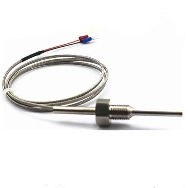
This table settles a common complaint: a fine-gauge probe that “should be good to 1260 °C” failing early at 1000 °C was never rated for that service in the first place. Mineral-insulated sheathed construction shifts the practical limit with sheath diameter in the same way.
Tolerance in numbers
Two tolerance systems cover Type K and they are closer than they look. ASTM E230 quotes a standard grade of ±2.2 °C or 0.75 percent of reading, whichever is greater, and special limits of error (SLE) of ±1.1 °C or 0.4 percent. IEC 60584-1 quotes Class 1 at ±1.5 °C up to 375 °C, then 0.004 times temperature to 1000 °C. Class 2 runs ±2.5 °C up to 333 °C, then 0.0075 times temperature to 1200 °C.
Run the numbers and the systems converge above their breakpoints, because 0.4 percent and 0.004t are the same slope, as are 0.75 percent and 0.0075t:
At 500 °C: SLE = Class 1 = ±2.0 °C; standard = Class 2 = ±3.75 °C
At 1000 °C: SLE = Class 1 = ±4.0 °C; standard = Class 2 = ±7.5 °C
The systems differ where plants rarely look. Near ambient the floors differ: ±2.2 versus ±2.5 °C for the standard grades, ±1.1 versus ±1.5 °C for the premium grades.
And the ceilings differ: Class 1 makes no claim above 1000 °C while ASTM tables keep quoting limits to 1260 °C. A 1100 °C specification written around Class 1 accuracy is therefore unenforceable as written. Tolerances for the other seven letters, plus the full Type K millivolt table, live in the types guide.
Drift mechanisms
Two failure modes belong specifically to Type K, and both involve the chromium in the positive leg.
Short-range ordering, sometimes called the K-state, develops when the wire soaks between roughly 250 and 600 °C. The Chromel lattice slowly rearranges and the local Seebeck coefficient rises. The reading drifts upward, by as much as a few degrees Celsius, worst when the service cycles in and out of that band. Cooling does not fully reset it.
Processes that sit in this window, where a degree or two matters, are the classic argument for switching to Type N. Its silicon-bearing alloys were designed against exactly this behavior.
Green rot sets in between about 815 and 1040 °C in low-oxygen, stagnant atmospheres, the conditions inside a long, tightly sealed protection tube. With too little oxygen to form a full protective oxide, the chromium oxidizes preferentially out of the Chromel leg. What remains is a greenish surface and a leg that is thermoelectrically closer to plain nickel.
Output falls, so the sensor reads low, an unsafe direction for a furnace control. Countermeasures include a ventilated or larger-bore protection tube so more air reaches the tip, sealed mineral-insulated construction, or again Type N, which resists the attack.
Extension and compensating wire
Between the connection head and the control system, ordinary copper breaks the measurement, as explained in our thermocouple basics guide. Type K runs use one of two matched cable grades, and the labels matter.
Extension wire (KX) uses the same nominal alloys as the sensor and is rated by IEC 60584-3 for use between −25 and 200 °C. Compensating cable (KCA or KCB) substitutes cheaper alloys that only mimic the K pair over a narrow band, at a looser tolerance class. The band is roughly 0 to 150 °C for KCA and 0 to 100 °C for KCB.
The cheaper cable is legitimate for a mild terminal environment and a long run. The error mechanism is the same in both cases: whatever temperature difference spans the transition points gets multiplied by the mismatch between cable and sensor behavior. Keep the cable inside its rated band and the added error stays within its published class. Let a compensating cable pass a hot ceiling void and the reading wanders with the weather.
Color codes are the other trap. Under the ANSI convention, Type K extension jackets are yellow, the positive conductor is yellow and the negative is red. That is the reverse of every DC instinct.
Under IEC 60584-3 the jacket and positive leg are green with a white negative. US thermocouple-grade wire commonly ships with a brown overall jacket. When in doubt, ignore the colors and use the magnet.
Checking a Type K
A suspect Type K can be screened at the bench in ten minutes with a multimeter, a magnet and two cups of water.
| Step | Expected result |
|---|---|
| 1. Magnet on each leg | The negative (Alumel) leg attracts weakly; the positive (Chromel) leg does not. Settles polarity on unmarked wire |
| 2. Resistance across the pair | A low reading, from a few ohms to tens of ohms depending on length and gauge. Open circuit means a failed element |
| 3. Tip in ice water, mV scale | A steady reading near −1 mV on a room-temperature bench, since the meter terminals act as the reference; log it as the ice-point value. A wandering reading suggests damaged or inhomogeneous wire |
| 4. Tip in boiling water | About 4.1 mV above the ice-point reading at sea level; altitude lowers the boiling point and trims the figure |
The mV checks are comparative, not a calibration: the meter’s own terminals form an uncompensated reference junction, so expect agreement within a few tenths of a millivolt rather than table-perfect values. Anything further off than that points at the drift mechanisms above, as does a probe that passes at the bench but disagrees with a trusted reference in the process. Drifted wire is replaced rather than adjusted.
Ordering notes
A complete Type K specification names the tolerance grade (standard or SLE, Class 1 or Class 2), the junction style, and sheath or protection tube material and diameter. Add insertion length, the process connection, and the head or lead termination. Pair it with matched extension cable, or put a temperature transmitter in the head and run copper. Our thermocouple assemblies page covers the build options, and a thermowell keeps the element replaceable on lines that cannot be opened.
Application example
Oil and gas operator, Pakistan. An RFQ specified Type K thermocouple assemblies for 0 to 1250 °C service with 1/2 in. NPT tapered threads and compression fittings, each paired with a temperature transmitter. We proposed the assemblies and transmitters to that specification; a requested calibration software kit sat outside our scope, so the quotation covered the measurement chain and left the software line open.
Below Type K the base metal choice narrows to three, compared in our Type J, T and E guide. Above it the platinum types take over, covered in the Type S, R and B guide.
Cable grades, the KX and KC options, resistance per gauge and how far a run can go are covered in our guide to thermocouple extension wire.
For the cross-type procedure behind those checks, including what resistance to expect from a given gauge and how to tell a failed element from a failed input card, see our guide to testing a thermocouple.
To turn a measured Type K millivolt reading into a temperature, with the reference junction handled for you, use our thermocouple mV to temperature calculator.
FAQ
What is the temperature range of a type K thermocouple?
The reference table spans −270 to 1372 °C, but usable figures are narrower. ASTM establishes −200 to 1260 °C for heavy protected wire, IEC tolerance classes cover −40 to 1200 °C, and about 1100 °C is the common ceiling for continuous service.
How accurate are type K thermocouples?
Standard grade holds ±2.2 °C or 0.75 percent of reading, whichever is greater; special limits of error tighten that to ±1.1 °C or 0.4 percent. Above about 375 °C, IEC Class 1 matches SLE and Class 2 matches the standard grade almost exactly. At 500 °C the premium grades work out to ±2.0 °C.
What is the difference between type K and type N thermocouples?
Type N uses silicon-bearing Nicrosil and Nisil alloys designed to resist the two Type K drift mechanisms, short-range ordering around 250 to 600 °C and green rot in low-oxygen heat. The trade is a weaker signal at low temperatures and a higher wire price, so N is chosen where K is known to drift.
What are the common problems with type K thermocouples?
The usual failures are drift from short-range ordering between roughly 250 and 600 °C, and green rot in oxygen-starved protection tubes between about 815 and 1040 °C. Reversed extension wire and fine-gauge wire run above the temperature its diameter supports are the other classic culprits.
How does a Type K thermocouple work?
Like every thermocouple, it produces a millivolt signal from the temperature difference between its measuring junction and its reference junction, about 41 microvolts per degree Celsius on average. The instrument compensates for the reference temperature and converts the voltage through the Type K reference table.
Request a quote
Tell us the application: operating and maximum temperature, atmosphere, insertion length, process connection and the control-system input. We will propose a Type K build, or a Type N where the service argues for it. Reach our application engineers or use the form below.
Written and technically reviewed by Wu Peng and the Instranova engineering team.