By Wu Peng, Senior Process Instrumentation Engineer · Last reviewed September 20, 2026
There are three checks that decide whether a thermocouple is good: continuity and resistance across the pair, millivolt output against a known temperature, and a substitution test that separates the instrument from everything upstream of it. All three take a digital multimeter. What changes is the pass mark, and it changes completely depending on whether the sensor drives a gas valve or feeds a process instrument.
Published procedures usually run the two together. A pilot thermocouple is a tiny generator that has to hold a valve magnet open, so it is judged in millivolts under load. A process thermocouple is a signal source that an instrument reads and cold-junction compensates, so it is judged on loop integrity and agreement with a reference.
Below are the numbers for both. They include the resistance figures that answer how many ohms a healthy pair should read, and the burnout behavior that explains why a dead sensor can show full-scale heat.
Contents
- Pilot or process sensor
- Checks at a glance
- Resistance and continuity
- Millivolt checks
- Pilot thermocouple values
- Isolating the fault
- Burnout drive direction
- Symptoms and causes
- Cleaning and its limits
- Verification against calibration
- FAQ
Pilot or process sensor
Before a meter comes out, settle which device is on the bench. A pilot thermocouple in a water heater, furnace or fireplace is wired to a millivolt safety valve and nothing else. It generates the current that keeps the valve magnet energized, so a unit that reads beautifully open-circuit can still fail the only test that matters, which is holding the valve in. Appliances that run a wall thermostat from the pilot use a multi-junction generator instead, covered in our comparison of thermopiles and thermocouples.
A process thermocouple runs to a transmitter, PLC input card or panel instrument. It supplies a few tens of millivolts that the instrument converts using cold junction compensation, covered in our guide to how a thermocouple works. Here the sensor supplies no useful power at all, and the pass mark is an unbroken loop plus a reading that tracks a known temperature.
| Question | Pilot thermocouple | Process thermocouple |
|---|---|---|
| What it drives | A gas valve magnet, directly | A transmitter or instrument input |
| Pass mark | Millivolts under load, plus drop-out | Loop continuity and agreement with a reference |
| Test with flame | Yes, the pilot is the heat source | No, use boiling water or a dry block |
| Typical failure | Pilot will not stay lit when the knob is released | Reading pinned at one end of the range, or drifting |
| Replacement cost | A stock part, usually changed on sight | Worth isolating first, since wiring is often the fault |
The rest of this guide marks each procedure for one column or the other. Mixing the two pass marks is how a bench test ends up clearing a part that fails in service.
Checks at a glance
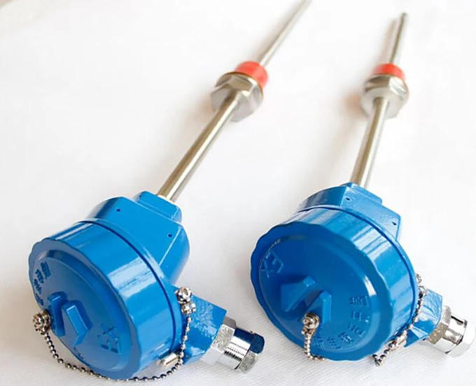
Reduced to a sequence, how to test a thermocouple runs to five steps: the three checks above, with a visual pass first and a leg-to-sheath reading alongside the resistance measurement. Each one narrows the problem before the next costs any time, and the visual, resistance and leg-to-sheath steps need nothing but a multimeter and the sensor disconnected at the instrument.
| Check | Expected result | What it rules out |
|---|---|---|
| Visual | Sound sheath, clean junction, tight terminals | Crushed sheath, loose screws, scale on the tip |
| Continuity and resistance | A few ohms to a few hundred, set by gauge and length | An open element or a broken lead |
| Leg to sheath | Open on an ungrounded build, continuous on a grounded one | Moisture in the insulation, unexpected grounding |
| Millivolts | Rises smoothly with tip temperature, no jumps | Inhomogeneous wire, reversed polarity |
| Substitution | Instrument reads terminal ambient with input shorted | A faulty input card or failed compensation |
Resistance and continuity
To test a thermocouple with a multimeter, start on the ohms range. A thermocouple should show continuity: the two legs are welded together at the tip, so an ohmmeter across the pair completes a circuit through the weld and back. An open circuit means a broken element or lead, and it is the failure this check exists to catch. What continuity does not prove is accuracy: a badly drifted sensor still reads as a closed loop.
The useful question is how many ohms to expect, and the answer is set by wire gauge and run length rather than by the sensor. Manufacturer tables publish loop resistance as ohms per double foot, meaning both conductors, out and back, for each foot of run. Multiply the table figure by the length in feet.
Loop resistance = ohms per double foot × run length in feet
Type K, 20 AWG, 50 ft run: 0.588 × 50 = 29.4 ohms
| Gauge | Ohms per double foot | Healthy reading on a typical run |
|---|---|---|
| 14 AWG | 0.147 | 1.47 ohms over 10 ft |
| 16 AWG | 0.232 | 4.64 ohms over 20 ft |
| 20 AWG | 0.588 | 29.4 ohms over 50 ft |
| 24 AWG | 1.488 | 119 ohms over 80 ft |
| 28 AWG | 3.59 | 180 ohms over 50 ft |
Type K values at 68 °F (20 °C), cross-checked between two published wire tables that agree within a few percent. Stranded conductors read slightly lower than solid. Figures for the same gauge vary between suppliers, so treat the column as a sanity band rather than a specification.
That band is why a fixed threshold misleads. A widely repeated rule says a healthy thermocouple reads under 100 ohms, yet the 24 AWG row above shows 119 ohms on an ordinary 80 ft run with nothing wrong. Judge the number against gauge and length, not against a single ceiling. The same tables drive the voltage drop arithmetic in our guide to extension and compensating cable, where the concern is measurement error rather than a broken circuit.
One more resistance check pays for itself. With one probe on a leg and the other on the sheath, an ungrounded assembly reads open and a grounded one reads continuous. On mineral-insulated sensors a low but not zero reading usually means moisture in the magnesium oxide, which drives insulation resistance down and can often be driven back out by baking. ASTM E780, the test method for this measurement, uses 500 VDC and notes that above 100 megohms the readings themselves start to scatter.
Why the two builds exist and which one to order is a selection question, covered in our junction style guide.
Millivolt checks
Switch to the millivolt range and the sensor becomes readable. Remember what the meter is doing: its own terminals form an uncompensated reference junction, so the display shows the difference between the tip and the meter, not absolute temperature. For Type K the NIST reference table puts 0 °C at 0.000 mV and 100 °C at 4.096 mV, both relative to a 0 °C reference.
The most useful field version compares two readings taken at the same moment. Note the millivolts at the sensor terminals, convert with a reference table, then read what the instrument displays. Agreement within a few tenths of a millivolt says the sensor and the instrument share the same view. A large gap points at compensation, wiring or the input card, and the next section separates those.
Watch the trend rather than the number. Warming the tip by hand or with hot water should raise the reading smoothly. A figure that falls as the process heats up means the polarity is reversed somewhere, an error with arithmetic worked through in the extension wire guide.
Jumpy or wandering millivolts on a steady bath suggest damaged or inhomogeneous wire. For a bench sequence built around a magnet, ice water and boiling water on one specific type, see the checks in our Type K guide.
Boiling water is a moving target. Water boils near 100 °C at sea level and drops roughly 1.1 °C for every 305 m of altitude, so a bench at 1,500 m boils near 95 °C.
Pilot thermocouple values
Gas appliance work has its own set of numbers, and they only make sense as a group of three. Published manufacturer figures put open-circuit output at 26 to 32 mV for a standard 30 mV thermocouple.
Measured with the valve connected and the knob held in, one manufacturer test procedure expects about 18 mV from a new thermocouple. A companion valve in the same manual quotes 19 mV as a minimum. The third reading is drop-out, taken as the flame dies.
| Reading | How it is taken | Published figures |
|---|---|---|
| Open circuit | Thermocouple disconnected, tip in the pilot flame | 26 to 32 mV for a 30 mV unit, per the product catalog |
| Closed circuit | Valve connected and energized, knob held in | About 18 mV new in one valve manual; a service rule of thumb puts it near half the open-circuit value |
| Drop-out | Flame extinguished, watch the value where the valve releases | One maker states the power unit should hold to 3 mV; another judges a fall of 5 mV or more from the stabilized reading; service guidance quotes 1 to 2 mV as normal |
These come from different manufacturers and are not interchangeable. Drop-out in particular is quoted two incompatible ways, as an absolute floor and as a relative fall, so follow the manual for the valve in front of you.
The reason open-circuit testing misleads is ordinary circuit theory. A thermocouple is a low-voltage source with its own internal resistance, and the valve magnet is a low-resistance load. One valve manual lists the coil at 3.6 ohms maximum alongside the 18 mV loaded figure. Those two numbers sit exactly where a source resistance near 2.4 ohms would put them.
30 mV × 3.6 / (3.6 + 2.4) = 18.0 mV at the valve
So a unit that measures a healthy 30 mV disconnected may still deliver too little under load to hold the magnet in. This is why a pilot that relights but will not stay lit can pass an open-circuit test. Where published procedures stop at the disconnected reading, take the loaded and drop-out values as well before deciding the valve is at fault.
Isolating the fault
On a process loop the sensor is only one of three suspects. The other two are the extension wiring and the instrument itself, and a short jumper settles which is which faster than any other test. The procedure works because the instrument compensates its own terminals.
| Test point | Action | Conclusion |
|---|---|---|
| Instrument input | Disconnect the loop and short the two input terminals | A display near terminal ambient clears the instrument and its compensation |
| Instrument input | If a plain jumper is rejected, twist a short piece of matching thermocouple wire into a junction and connect that | Same conclusion for inputs that require a real junction |
| Midpoint box | Open the nearest junction box and measure ohms toward the sensor | Open toward the sensor blames the probe; open toward the panel blames the cable |
| Sensor head | Lift both legs and measure the element alone | Removes terminal blocks and head transmitter from the result |
Two practical notes. Matching wire matters when you improvise a junction, because copper against a thermocouple alloy creates a second thermal joint and shifts the reading. And if the loop runs through a head-mounted transmitter, test on the sensor side of it first, since the transmitter output is a 4-20 mA current loop rather than millivolts.
Burnout drive direction
A modern transmitter or input card does not just stop reporting when the sensor opens. It detects the break and forces its output to a preset end of the range, a behavior called burnout or fail-safe drive. That is why a snapped element can display full-scale heat instead of nothing, and why the display alone cannot tell you a sensor has failed.
The direction is a configuration choice rather than a fixed default. One widely used temperature transmitter sets it with a failure mode switch on the electronics, offering fail high or fail low. Another treats it as an application choice; on one of its communication protocols the direction is set by a selector on the transmitter itself. Check how the loop in front of you is configured before reading anything into the value on the screen.
| Condition | Standard alarm limits | NAMUR compliant limits |
|---|---|---|
| Fail high | 21.75 to 23.0 mA | 21.0 to 23.0 mA |
| High saturation | 20.5 mA and above | 20.5 mA and above |
| Low saturation | 3.90 mA and below | 3.8 mA and below |
| Fail low | 3.75 mA and below | 3.6 mA and below |
Limits published for one transmitter series, in its standard and NAMUR compliant modes. Reading loop current directly is often quicker than interpreting the display in engineering units.
The practical consequence is worth spelling out. On a loop set to fail high, a broken Type K element can present as a reading at the top of the configured range, which may be enough to trip an interlock. Reading the loop current settles it immediately, because a genuine process value sits inside 4 to 20 mA while an alarm state sits outside the saturation limits.
Symptoms and causes
A fault is easier to describe than to measure, so it tends to arrive as a display symptom rather than a number. This table maps the common signs of a bad thermocouple to the check that confirms or clears each one.
| What you see | Likely cause | Confirm with |
|---|---|---|
| Pinned at one end of the range | Open element driving the configured burnout direction | Ohms across the pair, then loop current |
| Sits near the terminal temperature | Loop broken but compensation still working, or legs shorted together | Resistance at the head, then at the midpoint box |
| Reads low and falls as the process heats | Polarity reversed at a terminal | Millivolts while warming the tip |
| Slow downward drift over months | Alloy aging, including green rot on Type K | Comparison against a reference probe |
| Unstable or noisy | Ground loop, damp insulation or a loose terminal | Leg to sheath resistance, terminal torque |
| Sluggish response | Deposits on the tip or a loose fit in the thermowell | Visual check, step change in a water bath |
| Error changes with panel temperature | Copper wire in place of extension cable | Inspect the cable type at every terminal |
Two of these rows route elsewhere. Drift on Type K has its own mechanisms and temperature bands, set out in the Type K guide. A sluggish sensor is often a fit problem inside the thermowell rather than a sensor fault. If the type itself is unknown, the identification methods in our thermocouple types guide come before any of this, since the expected millivolts depend on it.
Cleaning and its limits
Cleaning helps in one world and not the other, which is why the answer circulating online contradicts itself. On a pilot thermocouple, soot on the tip insulates the junction from the flame and starves the output. Published gas appliance guidance has technicians take the deposit back to bright metal with fine abrasive paper, 220 grit or finer. The same guidance warns against steel wool, because loose fibers can short terminals or block a burner.
On a process thermocouple, cleaning restores response time and nothing else. Scale and product buildup slow the sensor down, so removing them is worth doing. What cleaning cannot touch is the alloy itself.
Once chromium has oxidized out of the positive leg on a Type K, the leg turns magnetic and the output drifts negative. Manufacturer guidance describes preventive measures that minimize but do not eliminate that oxidation. No published method reverses it.
The dividing line is simple enough to apply at the bench. Cleaning restores heat transfer. It does not restore thermoelectric output. A sensor that still reads wrong after cleaning is telling you the wire itself has changed, and it needs replacing rather than servicing.
Verification against calibration
Everything above is verification. A multimeter, a jumper and a pot of boiling water answer whether the loop is intact and roughly right, which is what a shift team needs during a callout. None of it produces an uncertainty figure or a traceable record, so none of it is calibration.
Calibration means comparing against a reference with known traceability, usually a dry block or reference probe, and recording as-found and as-left data. The distinction, including where adjustment fits, is set out in our guide to calibration against verification. Both have a place: verification catches the failures, calibration quantifies the error.
Application example
Oil and gas, South Asia. A buyer specifying Type K thermocouples for 0 to 1250 °C with matching temperature transmitters also asked for a calibration kit built around vendor software and a dongle. We could not supply that kit. The proposal separated the two needs instead: routine field verification with a multimeter and the substitution test above, with traceable calibration handled by a laboratory when records are required.
We supply thermocouple assemblies and temperature transmitters configured to the range and junction style you specify. The sensor type and wire gauge are stated on the order, so the resistance figures above are the ones you should measure.
FAQ
How can I tell if my thermocouple is faulty?
To check a thermocouple quickly, measure resistance across the pair first. An open circuit means a broken element or lead and confirms the fault. If the pair reads normally, short the instrument input terminals: a display near room temperature clears the instrument, which points the fault back at the sensor or its wiring. On a gas appliance, measure millivolts with the valve connected rather than disconnected.
How many ohms should a thermocouple be?
There is no single figure, because the reading is set by wire gauge and run length rather than by the sensor. A short 14 AWG assembly reads close to 1.5 ohms, while 80 feet of 24 AWG reads about 119 ohms and is perfectly healthy. Multiply the ohms per double foot for your gauge by the run length, then compare.
Can you clean a thermocouple and make it work?
Sometimes. On a pilot thermocouple, removing soot from the tip restores the heat reaching the junction and often restores output. On a process thermocouple, cleaning removes deposits and improves response time but cannot reverse alloy aging. If the reading is still wrong after the tip is clean, the wire has changed and the sensor needs replacing.
Should a thermocouple have continuity?
Yes. The two legs are welded at the measuring junction, so an ohmmeter across the pair should complete a circuit. No continuity means the element or a lead is open. Continuity on its own proves only that the circuit is unbroken, not that the sensor is accurate, so follow it with a millivolt comparison against a known temperature.
Request a quote
Tell us the process temperature, the sensor type and the run length. We size the assembly and the extension cable together, so the installed loop resistance is known before it ships. Reach our application engineers or use the form below.
Written and technically reviewed by Wu Peng and the Instranova engineering team.