Flow Meters › Fire Pump Flow Meter
Fire Pump Flow Meter
A fire pump flow meter measures the water a stationary fire pump delivers during its performance tests. NFPA 25 requires an annual test of each pump at churn, at rated flow, and at 150 percent of rated flow. The meter is the instrument that proves those points. It lives on a test line or a recirculation loop off the pump discharge and reads in GPM, L/min, or m3/h.
Two other products share the name and are not covered here. A utility fire service meter is a billing meter on the water line feeding a sprinkler system. A truck-mounted apparatus flow meter reads the discharges of a fire engine. This page is about a flow meter for fire pump testing: metering a fixed fire pump under NFPA 20 and NFPA 25.
Catalog pages for this product usually present one venturi meter and stop there. The selection work sits upstream: which measuring principles satisfy the test, how large the meter must read, and when a meter may replace discharged water at all. The standards set those rules, and this page puts numbers on them.
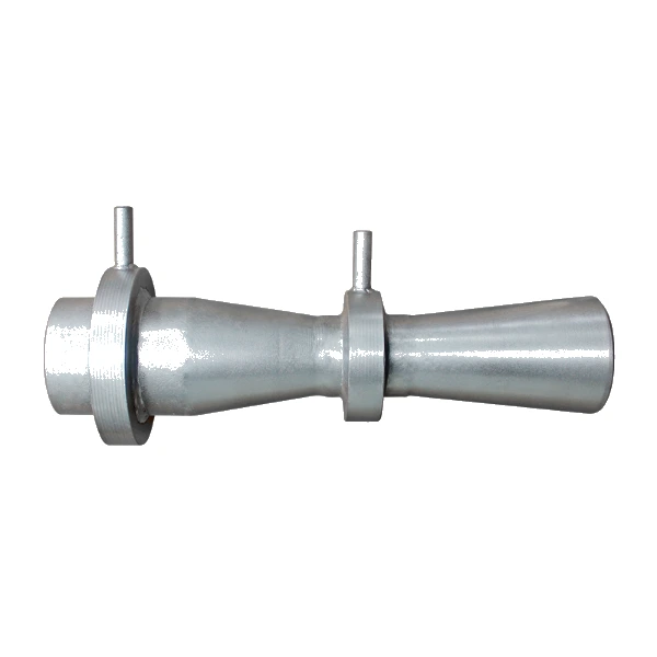 Venturi Flow Meter
The measuring element inside most dedicated fire pump test meters: a calibrated venturi read by a differential pressure gauge, with no moving parts in the water.
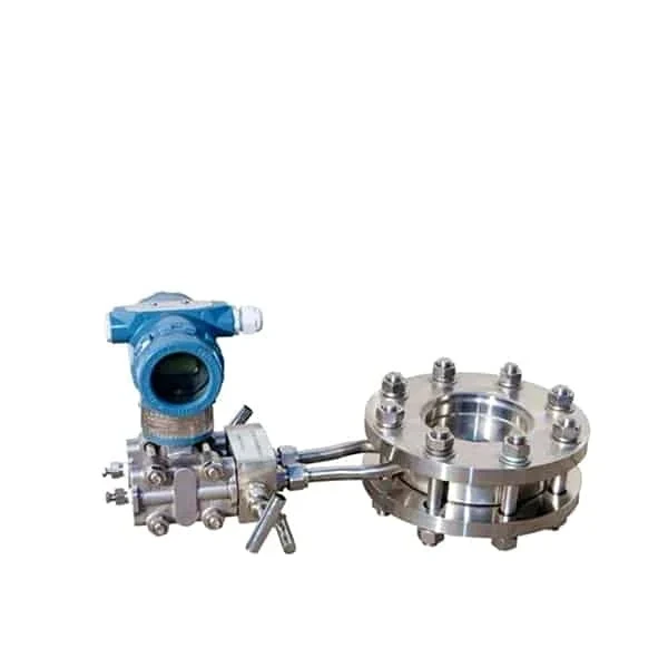 Orifice Plate Flow Meter
A differential pressure element with a known discharge coefficient; NFPA 25 accepts listed orifices as test devices, and the plate is the lowest-cost element.
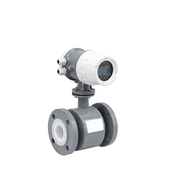 Magnetic Flow Meter
Full-bore, obstruction-free metering of fire water with 0.5 percent accuracy and a 4-20 mA output for recording the whole test curve.
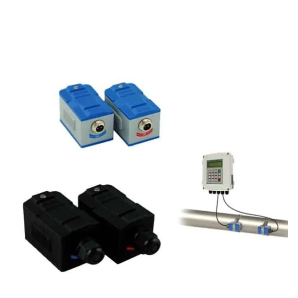 Clamp-On Ultrasonic Flow Meter
Straps to the outside of the pipe to cross-check an installed test meter or read a discharge line without cutting pipe or draining the system.
Choosing a test meter
Every dedicated fire pump test meter on the market reads flow the same way. A venturi or another differential pressure element sits in the line, with a direct-reading GPM dial across the pressure taps. That is a sound default, but it is not the only principle that can hold the accuracy the test needs. The table compares the options.
| Technology | How it reads | Typical accuracy | Role in pump testing |
|---|---|---|---|
| Venturi | Differential pressure across a calibrated throat | 0.5 to 2% of reading as a packaged test meter, by make | The standard element in permanent test loops; low permanent pressure loss |
| Orifice plate | Differential pressure across a bored plate | About 1% with a calibrated DP reading | Lowest-cost element; NFPA 25 accepts listed orifices with a known coefficient |
| Magnetic | Voltage induced by the moving water | 0.5% of reading | Test lines that discharge to a tank or drain; logs the curve through 4-20 mA |
| Clamp-on ultrasonic | Transit time of sound across the pipe | About 1% of reading, installation dependent | Verifying an installed meter or reading a line with no meter fitted |
| Paddlewheel (portable) | Rotor speed in a hose-end flow tube | Field instrument class; per model datasheet | Portable testers on hose discharges; not a permanent loop meter |
One requirement sits above the table: where the authority having jurisdiction calls for a listed or FM-approved test device, the meter must carry that approval regardless of principle. State the approval requirement in the inquiry before sizing starts.
What NFPA 25 requires
NFPA 25 (2017 edition numbering; clauses shift between editions) sets the test the meter serves. Clause 8.3.3.1 requires an annual test at no flow, at rated flow, and at 150 percent of rated capacity, flowed through approved test devices. If the suction supply cannot deliver 150 percent, the pump is tested to the maximum discharge the supply allows.
The standard also decides when a meter may stand in for discharged water. At least every third year, the annual test must physically move water out of the loop: hose streams, or a meter discharging to a drain or reservoir. In the other two years, a closed recirculation loop back to pump suction is permitted. The arrangements section below maps each option to its metering equipment.
Electric pumps run at least 10 minutes for the test and diesel pumps at least 30. The results are compared with the original acceptance curve, and a drop of more than 5 percent calls for an investigation. The meter itself is regulated too. Flow meters must be calibrated annually to an accuracy of plus or minus 3 percent, while the test gauges and transducers around them are held to plus or minus 1 percent.
Sizing to 175 percent
NFPA 20 sizes the measuring equipment at installation: the test device must be capable of passing water at no less than 175 percent of rated pump capacity. A 1,000 GPM pump therefore needs a meter and test line good for 1,750 GPM, not one that tops out at the 1,500 GPM test point. Packaged test meters handle this with dials scaled from 50 to 200 percent of the pump rating, which brackets the churn-to-150-percent test with margin.
| Pump rating | 175% capacity | Typical dial range | Rated flow, metric |
|---|---|---|---|
| 500 GPM | 875 GPM | 250 to 1,000 GPM | 114 m3/h |
| 750 GPM | 1,313 GPM | 375 to 1,500 GPM | 170 m3/h |
| 1,000 GPM | 1,750 GPM | 500 to 2,000 GPM | 227 m3/h |
| 1,500 GPM | 2,625 GPM | 750 to 3,000 GPM | 341 m3/h |
| 2,500 GPM | 4,375 GPM | 1,250 to 5,000 GPM | 568 m3/h |
Metric works the same way through the conversion 1 GPM = 3.785 L/min = 0.227 m3/h. Most published meter data stops at GPM, so the metric column above is worth keeping for projects specified in m3/h. The flow rate units guide covers the full conversion set.
Closed loop or discharge
NFPA 25 recognizes three ways to flow the annual test, and the meter plays a different part in each.
| Arrangement | Where the water goes | Measurement | Permitted cadence |
|---|---|---|---|
| Hose streams | Out of the test header to a safe discharge point | Pitot readings at each nozzle, summed | Any year; one of the two options required at least every third year |
| Meter to drain or reservoir | Through the bypass meter, then out of the loop | The flow meter reads the whole curve directly | Any year; also satisfies the every-third-year rule |
| Closed loop to suction | Recirculated from discharge back to pump suction | The flow meter is the only measurement | Two years out of every three |
The closed loop has a limit worth understanding before relying on it. Recirculating water around the pump tests the pump alone. The suction supply never gets exercised, so a failing city main or a blocked suction screen stays invisible. That is the engineering reason behind the every-third-year discharge requirement.
A loop that returns to a storage tank sits in between, since the pump then draws from and returns to the real supply.
Two safeguards attach to closed-loop testing. The temperature of the recirculating water must be monitored, because the pump adds heat to the same water on every pass. And if the closed-loop results disagree with the previous annual test, the test must be repeated with a discharging arrangement. The alternative is to recalibrate the meter and run the test again.
Installing the meter loop
The metering line tees off the pump discharge between the check valve and the discharge control valve. It runs through two normally closed valves with the meter between them, and returns to suction, a tank, or a drain. NFPA 20 adds a detail that surprises many first installations. When the meter sits in a recirculation loop, an alternate way of measuring flow must also be provided, which in practice means a test header or connection stays in the design.
Straight pipe decides whether the dial reading means anything. Venturi test meter makers commonly require about five pipe diameters straight upstream of the meter and two downstream. Elbows close to the meter leave the needle swinging with the turbulence instead of settling on a value.
If the room cannot give the meter that run, expect an unsteady reading at 150 percent flow, and lay the return line out in a larger size to slow the water. Exact fire pump flow meter installation distances are on the manufacturer sheet for each meter. The DP-type meters follow the same physics as any differential pressure flow meter.
On commissioning day, purge the gauge lines. A DP dial with air trapped in its sensing hoses reads wrong in either direction, so the operating drill of every venturi test meter starts by bleeding both hoses until they run solid water.
Calibration
Fire pump flow meter calibration is an annual requirement, not a factory-only event. NFPA 25 holds the meter to plus or minus 3 percent, checked once a year. Suppliers handle this with NIST-traceable calibration of the meter or its gauge. The paperwork belongs in the pump test records, because an inspector who doubts the curve asks for the calibration certificate first.
A meter that drifts shows up as a test curve that shifts without a mechanical explanation. The closed-loop rule above turns that into a procedure: inconsistent result, then recalibrate, then retest. General method and interval logic for process meters is covered in the flow meter calibration guide.
Hose streams and pitot
In the hose stream years there is no meter in the flow path. Each nozzle is read with a pitot gauge and converted with the discharge formula Q = 29.83 c d2 √p, with d the nozzle diameter in inches and p the pitot pressure in psi.
Worked through: a 1.75 inch smooth-bore tip at 60 psi with c = 0.97 flows 29.83 x 0.97 x 3.0625 x 7.75, about 686 GPM. Some references print the constant as 29.84. Both are roundings of the same derivation, and the difference is far below field reading accuracy.
Testers plan on roughly 500 GPM per hose line. The 150 percent point of a 1,500 GPM pump is 2,250 GPM, which takes about five simultaneous streams, each with its own pitot reading. That crew-and-water cost is exactly what a permanent metered test line removes in the two intermediate years.
Application example
Pump test stand, India. An inquiry covered flow measurement on a water test stand with DN200 and DN400 lines running up to 120 m3/h. Proposed: full-bore magnetic flow meters on both lines, each with a local display and a digital output to the test-stand PLC, so every run is read at the panel and logged. The same full-bore approach serves permanent pump test lines that discharge to a tank or reservoir.
FAQ
How to test a flow meter on a fire pump?
Cross-check it against an independent measurement. The direct route is a hose stream test: flow the same points through the test header, convert the pitot readings, and compare with the meter dial. A clamp-on ultrasonic meter on the test line gives a second reading without any discharge. If the meter disagrees beyond about 3 percent, send it for recalibration; NFPA 25 requires that annually in any case.
What are the requirements for NFPA 25 fire pump testing?
Weekly or monthly no-flow churn runs, plus an annual flow test at churn, 100 percent, and 150 percent of rated capacity. Electric pumps run at least 10 minutes and diesel pumps at least 30. Results are compared against the original acceptance curve, and a drop of more than 5 percent triggers an investigation. At least every third year the test must discharge real water rather than recirculate it through a closed metering loop.
How to calculate LPM of fire pump?
Multiply the GPM rating by 3.785. A 1,000 GPM fire pump is rated 3,785 L/min, which is also 227 m3/h. The annual test then runs the pump at 100 percent of that figure and at 150 percent, which is 5,678 L/min. A meter and test line sized in metric must carry those numbers, not just the nameplate rating.
What are the different types of fire pump flow tests?
Routine no-flow tests, weekly or monthly, confirm the driver starts and runs. The annual flow test measures real performance and can be flowed three ways. Those are hose streams read by pitot gauges, a bypass flow meter discharging to a drain or reservoir, and a closed metering loop back to pump suction. The closed loop is the least disruptive but is limited to two years out of three because it never tests the suction supply.
Request a quote
Tell us the pump rated capacity, the line size, and whether the meter discharges to drain, tank, or back to suction. If the authority having jurisdiction requires a listed or FM-approved test device, state that first. We size the meter to the 175 percent rule, configure the display and outputs, and confirm the pressure rating.