By Wu Peng, Senior Process Instrumentation Engineer · Last reviewed September 2, 2026
The dielectric constant of the product sets how much of a radar pulse bounces back from its surface. That decides whether a radar level transmitter will see the surface at all. Water, with a relative permittivity of about 80, reflects 64 percent of the incident power. Diesel, at about 2.1, reflects 3.4 percent, nineteen times less.
Below a value of roughly 1.4 the echo is so weak that only a guided wave radar with special end-of-probe processing can track it. The number is not a pass or fail threshold on its own; it is a signal budget, and this page shows how to read it.
Vendors quote minimum dielectric constants of 1.1, 1.4, 1.6, 2 and 4 for what sounds like the same instrument. The published tables disagree with each other on ethanol, sulfuric acid and even demineralized water. This guide explains the reflection physics with worked numbers and reconciles those thresholds against the dynamic range of the electronics. It shows how to estimate a value the tables do not list, covers what temperature, concentration, foam and interface layers do to the reading, and ends with which radar to specify for each band.
Contents
- What dielectric constant means
- Reflection and dielectric constant
- Minimum dielectric constant
- Dielectric constants of media
- Estimating an unlisted value
- Temperature and concentration
- Low dielectric solutions
- Interface measurement
- Selecting the radar
- FAQ
What dielectric constant means
The dielectric constant, written εr and also called relative permittivity or DK, is the ratio of a material’s permittivity to that of a vacuum. Vacuum is 1.0 by definition, air is 1.0006, and everything a level transmitter looks at sits between about 1.2 and 100. Polar molecules such as water and alcohols have high values because their dipoles line up with the field. Non-polar hydrocarbons, plastics and dry powders have low values, typically 1.5 to 3, because there is nothing to line up.
Two points matter for radar and are often skipped. First, εr depends on frequency. The values in most tables are measured at low frequency; for water the value at 26 or 80 GHz is lower than the static 80, but still far above anything that would trouble a radar. For hydrocarbons the frequency dependence is negligible.
Second, it is the contrast between the product and what sits above it that matters. In a vented tank that is air at 1.0. Under a heavy hydrocarbon vapor blanket or high-pressure steam the vapor itself has a dielectric constant above 1, and both the reflection and the pulse speed change.
Reflection and dielectric constant
At normal incidence on a flat surface, the fraction of the electric field reflected at the boundary between air and a non-conductive product follows the Fresnel relation. Squaring it gives the fraction of power that comes back to the antenna. That is the number that matters to the receiver.
r = (√εr − 1) / (√εr + 1) R = r²
Diesel, εr = 2.1: r = (1.449 − 1) / (1.449 + 1) = 0.183, so R = 0.034, or 3.4 percent of the power. Water, εr = 80: r = 0.799, R = 63.8 percent.
A second version of this formula circulates without the square roots, written as (ε1 − ε2) / (ε1 + ε2). That is an impedance-mismatch shorthand and it gives the wrong numbers for radar. It puts water at 97.5 percent and diesel at 35 percent reflected, ten times too optimistic at the low end.
Use the square-root form. A related folk rule says the dielectric constant roughly equals the percentage reflected. It is close only between about 1.5 and 2.5 (at 2.0, R is 2.9 percent); at 8 the true reflection is 22.8 percent, not 8.
| Product | εr | Power reflected | Relative to air-water | Weaker than water |
|---|---|---|---|---|
| Water, 20 °C | 80 | 63.8% | 0 dB | 1× |
| Ethanol | 24 | 43.7% | −1.6 dB | 1.5× |
| Glass, ceramics, wet solids | 4 | 11.1% | −7.6 dB | 5.7× |
| Oils, most solvents | 3 | 7.2% | −9.5 dB | 8.9× |
| Diesel, crude oil | 2.1 | 3.4% | −12.8 dB | 19× |
| Hexane, light naphtha | 1.9 | 2.5% | −14.0 dB | 25× |
| Liquefied gases, LNG class | 1.6 | 1.4% | −16.7 dB | 47× |
| Plastic pellets, dry powders | 1.5 | 1.0% | −18.0 dB | 63× |
| Guided wave limit | 1.4 | 0.70% | −19.6 dB | 91× |
| End-of-probe range | 1.2 | 0.21% | −24.9 dB | 308× |
Normal incidence, flat calm surface, non-conductive product, air above. Conductive liquids (brines, acids) reflect nearly all the power regardless of the listed value. Calculated with the square-root Fresnel formula; the dB column is the return relative to a water surface.
Minimum dielectric constant
The minimum dielectric constant for a radar level transmitter is quoted anywhere from 1.1 to 4, depending on who publishes it. They are not contradictory once you treat them as a signal budget. Each number is the point where that instrument’s return drops below what its receiver can pull out of the noise. The table converts the thresholds into decibels relative to a water echo so they can be compared.
| Instrument class | Quoted minimum εr | Return vs water | Why the number is where it is |
|---|---|---|---|
| Pulse radar, 6 to 26 GHz, horn antenna | 2 to 4 | −7.6 to −13.4 dB | Wide beam spreads the power; older receivers have about 90 dB of dynamic range, and internals and nozzle echoes use up part of it. |
| FMCW radar, 80 GHz, lens antenna | 1.1 to 1.8 | −15 to −30 dB | Narrow 3 to 4 degree beam keeps the power on the surface; modern receivers claim about 120 dB, which is 30 dB or a thousand times more usable range than 90 dB. |
| Non-contact radar in a stilling well | 1.6 to 3 handled well | −9.5 to −17 dB | The pipe acts as a waveguide, so the power that would spread across the tank arrives at the surface and comes back concentrated. |
| Guided wave radar, single rod or cable | 1.4 standard | −19.6 dB | The probe carries the pulse to the surface with almost no spreading loss, so the whole budget goes to the reflection itself. |
| Guided wave radar, coaxial probe | 1.4, with more margin | −19.6 dB | The outer tube shields the pulse from nozzle and vessel-wall echoes; the usual choice for light hydrocarbons in chambers. |
| Guided wave radar with end-of-probe tracking | 1.2 or lower | −24.9 dB or weaker | The transmitter times the strong echo from the probe end, which arrives later the deeper the probe is immersed, and infers level from that delay instead of the surface echo. |
Quoted minimums are manufacturer statements gathered from published datasheets and application literature; dB values are calculated from the Fresnel formula for the quoted εr. Foam, turbulence, vapor and vessel internals all spend part of the same budget.
The practical reading of that table: above about 3, any radar works and the choice is about mounting, temperature and materials. Between 1.8 and 3, use 80 GHz through-air or a stilling well. Between 1.4 and 1.8, specify a guided wave radar.
Use a coaxial probe if the tank has internals or a nozzle longer than about 150 mm. Below 1.4, only guided wave radar with end-of-probe processing, or a different principle altogether.
Dielectric constants of media
The values below are the ones that recur across reference lists and that I have found consistent in the field. Where published tables disagree, the range is shown and the reason is given. The disagreement is usually the useful information.
| Medium | εr | Note for radar |
|---|---|---|
| Water, demineralized or raw | 80 | Purity does not change it; one widely copied list gives demineralized water as 29, which is wrong. |
| Aqueous acids, bases, brines | 50 to 80, conductive | Conductivity makes them near-perfect reflectors; the listed value is academic. |
| Sulfuric acid | published: about 9 at 97%, above 30 dilute | Concentration-dependent; tables that give a single number are quoting one strength. Any radar sees it. |
| Methanol, ethanol | 33, 24 to 25 | Some lists give ethanol as 16; both are polar and strongly reflective either way. |
| Acetone, ketones | 20 to 21 | Vapor is heavy; expect a small speed correction in closed tanks. |
| Glycerin, glycols | 37 to 46 | Viscous, coats probes; prefer non-contact. |
| Vegetable and mineral oils | 2.5 to 4 | Fine for 26 GHz on a calm surface; 80 GHz if agitated. |
| Diesel, kerosene, gasoline, crude | 1.8 to 2.3 | The classic low-dielectric case; 80 GHz or guided wave. |
| Hexane, heptane, naphtha | 1.9 | Guided wave with coaxial probe in a chamber is the safe answer. |
| LPG, LNG, liquid nitrogen | 1.4 to 1.8 | Cryogenic and pressurized; guided wave radar or differential pressure. |
| Plastic granules, dry cement, grain | 1.5 to 3 | Rises sharply with moisture; 80 GHz lens antenna aimed at the outlet. |
| Coal, ores, minerals | 2.5 dry to 7 wet | Moisture dominates; wet product is easier to measure than dry. |
Room temperature, low-frequency reference values unless noted. Two values from popular vendor lists that do not survive a check: sulfuric acid above 100, and demineralized water at 29.
Estimating an unlisted value
Most plant fluids are not in any table: a solvent blend, a proprietary additive, a hydrocarbon cut. Two methods get close enough to pick a radar. For non-polar liquids the dielectric constant is very nearly the square of the optical refractive index. Any lab can measure that, and most datasheets list it.
εr ≈ n² (non-polar liquids only)
Diesel, n = 1.46: εr ≈ 1.46² = 2.13, against a measured 2.1 to 2.2. Hexane, n = 1.375: 1.89, measured 1.89.
The rule fails for anything polar, because permanent dipoles add a contribution the optical index does not see. Water has n = 1.33, so n² = 1.77 against a real 80. For mixtures, no simple rule is reliable when one component is polar. The logarithmic mixing rule, ln ε = Σ vi ln εi by volume fraction, is the one that tends to fit.
For 30 percent ethanol in hexane it gives εr ≈ 4.1. A linear volume average gives 8.5 for the same blend, twice as optimistic. Size the radar for the lower estimate. If the blend matters commercially, send a sample to a lab for a dielectric measurement at 1 MHz; it costs less than one wrong transmitter.
Requests for a mixing rule that works for polar blends have sat unanswered on engineering forums for over a decade. That tells you how far to trust any single formula.
Temperature and concentration
Dielectric constant is not a fixed material constant. Water falls from about 88 at 0 °C to 80 at 20 °C and 55 at 100 °C. That is a 37 percent drop across the liquid range, still far above any radar limit. For hydrocarbons the temperature coefficient is tiny, a fraction of a percent per 10 K, and can be ignored.
What cannot be ignored is composition. Published values for sulfuric acid move from about 9 at 97 percent to above 30 when diluted, and a solids product moves from 2.5 dry to 7 wet as it takes on moisture. Density does the same for powders, so a fluidized bed reflects less than the same product settled.
The one temperature effect that does hit radar is in the vapor space, not the product. In a pressurized vessel the vapor above the liquid has a dielectric constant above 1. The pulse travels slower through it by the factor 1/√εvapor. High-pressure saturated steam is dense enough to put a guided wave radar reading out by up to 20 percent.
Transmitters with dynamic vapor compensation correct for it by timing the echo from a reference reflector at a known distance. For hydrocarbon vapor at a few bar the effect is under 1 percent. Check the vapor density before you check the liquid.
Low dielectric solutions
When the product sits in the red band of the chart, four things raise the odds, and they stack. Move to 80 GHz through-air radar. Its narrow beam and larger dynamic range are worth roughly 30 dB against an older 26 GHz horn, and that alone takes a 2.1 diesel from marginal to routine on a calm surface. Put the antenna in a stilling well or bypass chamber so the pulse cannot spread; our guide to stilling well design gives the pipe sizes and the vent hole rules.
Switch to guided wave radar, where the probe carries the pulse and the return is limited only by the surface reflection. The coaxial probe version is the one to specify for light hydrocarbons in a chamber. Below 1.4, use end-of-probe tracking, which reads the delay of the probe-end echo through the product rather than the surface echo itself.
Two things reduce the odds and are worth checking before blaming the dielectric constant. Foam on a low-dielectric liquid absorbs the little power that would have reflected; a few centimeters of foam on diesel can take the echo below threshold. Turbulence or splashing scatters the return away from the antenna. A guided wave probe is far less sensitive to this because the reflection is captured along the conductor, which is why it is often chosen for tanks filled from above.
Application example
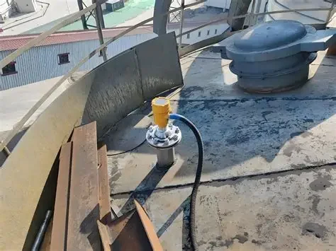
Fuel storage, Philippines. A site storing diesel and engine lubricating oil asked for flow and level instruments on 4-20 mA two-wire loops. For the level points, guided wave radar was proposed rather than through-air radar, because the surface is disturbed during filling and a probe-guided pulse is not scattered by splashing. Diesel and lube oil both sit near a dielectric constant of 2, where a guided probe has the larger margin. The proposal is at the parameter-confirmation stage.
Interface measurement
Guided wave radar can read two levels at once when a light, low-dielectric liquid floats on a heavy, high-dielectric one, oil over water being the textbook case. The first reflection comes from the top surface; the rest of the pulse continues down through the oil and reflects at the water. Three conditions have to hold.
The upper layer must be the lower dielectric of the two, and its value must be known and stable. The difference between the layers should be at least about 6 (some manufacturers say 10) so the second echo is distinct. The upper layer also has to be thick enough, typically 100 mm or more, for two echoes to separate in time.
The reason the upper value must be known is that the pulse slows inside it by 1/√εr. In oil at 2.0 it travels at 71 percent of its speed in air; at 4.0, at 50 percent. Enter 2.0 when the real value is 4.0 and a 500 mm oil layer is reported as 707 mm, an error of 207 mm on the interface position and on the oil volume.
That is the most common interface-radar complaint I see, and it is a configuration error, not an instrument fault. Emulsion layers between the two liquids smear the second echo and are the practical limit of the method.
Selecting the radar
Read the dielectric constant first, then the vessel. The routing below maps the bands in this guide onto instruments we build and onto the guides that cover the neighboring decisions.
| Product band | First choice |
|---|---|
| Water-based, acids, bases, εr above 10 | Any non-contact radar; choose by materials and mounting. See the 26 GHz radar level transmitter, or the radar level sensor for corrosive liquids with a PTFE antenna for acid vapor. |
| Oils, solvents, 3 to 10 | 26 GHz on a calm surface; 80 GHz radar level transmitter if the tank is agitated or the nozzle is long. |
| Fuels and light hydrocarbons, 1.8 to 3 | 80 GHz through-air, or a guided wave radar level transmitter where the surface splashes or the tank has internals. The tank-side detail is in our diesel tank level guide. |
| Liquefied gases and solvents, 1.4 to 1.8 | Guided wave radar with coaxial probe in a chamber, or differential pressure. Compare in level transmitter types. |
| Dry powders and granules, 1.5 to 3 | 80 GHz lens antenna aimed at the outlet; for tall silos the long range radar level sensor with a parabolic antenna. |
| Below 1.4, or foam-covered | Guided wave radar with end-of-probe tracking, or leave radar: a capacitance level transmitter reads low-dielectric liquids directly, and ultrasonic level sensors are unaffected by the dielectric constant. |
For a quote, send five things: the product and its dielectric constant if known (or the refractive index, or a sample); the operating temperature and pressure; the vapor above the liquid; the tank height and nozzle dimensions; and whether the surface is calm, agitated or foamed. The full range of antennas and probes is on the radar level sensors page.
The same permittivity arithmetic drives fuel-tank probes; the capacitive fuel level sensor guide works through the ethanol and water numbers.
FAQ
What dielectric constant is required for a radar level transmitter?
About 1.4 for a guided wave radar, roughly 1.8 for an 80 GHz through-air radar on a calm surface, and 2 to 4 for older 26 GHz horn-antenna units. Below 1.4 a guided wave radar with end-of-probe tracking can still read level. The threshold is a signal budget, so foam, turbulence and long nozzles raise it.
How does dielectric constant affect radar level measurements?
It sets the fraction of the pulse reflected at the surface: about 64 percent for water at 80, 3.4 percent for diesel at 2.1, and under 1 percent below 1.5. A weaker echo is harder to separate from nozzle and vessel echoes. Low values therefore push the choice toward 80 GHz, a stilling well or a guided wave probe.
How do you measure dielectric constant?
A laboratory measures it as the capacitance ratio of a cell filled with the liquid against the same cell empty, usually at 1 MHz. Without a lab, look it up for pure products, square the refractive index for a non-polar liquid (diesel at n = 1.46 gives 2.13), or use the logarithmic volume mixing rule for blends as a lower estimate.
What is a low dielectric constant?
For radar level measurement, anything below about 3: oils, fuels, solvents, liquefied gases, plastics and dry powders. In that band the surface reflects under 7 percent of the pulse, and below 1.8 about 2 percent, which is where frequency, antenna, stilling well and probe type decide whether the transmitter sees the surface.
Can radar measure low dielectric liquids like oil?
Yes. Oils and fuels between 1.8 and 3 are measured routinely with 80 GHz radar on a calm surface or with guided wave radar where the tank is agitated or has internals. Liquefied gases near 1.5 need a guided wave radar with a coaxial probe or end-of-probe processing.
Request a quote
Tell us the product, its dielectric constant or refractive index, the vapor and temperature above it, and the tank geometry. We will match the frequency, antenna and probe to the signal budget, not to a catalog page. Reach our application engineers or use the form below.
Written and technically reviewed by Wu Peng and the Instranova engineering team.