By Wu Peng, Senior Process Instrumentation Engineer · Last reviewed August 02, 2026
A diesel tank level gauge reports how much fuel is left in a storage tank. On industrial tanks the practical choice is between a mechanical float gauge, a magnetostrictive or hydrostatic transmitter, and non-contact ultrasonic or radar. Two fuel properties and one contaminant decide which one works. Density runs 820 to 845 kg/m³ at 15 °C under EN 590. A dielectric constant near 2.1 returns only about 3.4 percent of the radar power a water surface returns. Water then collects under the fuel, where it biases every pressure-based reading.
Most selection guides stop at a list of technologies. This one gives the numbers that decide the job: how density turns head into volume, and why a water-calibrated transmitter under-reads diesel by 16 percent. It also covers what a water bottom does to the indication, and where the alarm points sit on a generator day tank. For how each sensing principle works in general, see our guide to level transmitter types; this page stays on fuel.
Contents
- Why diesel behaves differently
- Gauge and sensor options
- Head to volume
- Water at the bottom
- Day tank alarm points
- Hazardous area classification
- Checking against a dip
- Choosing by tank
- FAQ
Why diesel behaves differently
Diesel is not water with a different color, and three of its properties change the instrument choice.
Density. EN 590 sets diesel density at 820 to 845 kg/m³ at 15 °C. Every pressure-based level reading is a density calculation, so that band is not a detail. It is also not constant: the same tank warms and cools, and a winter blend is not a summer blend.
Dielectric constant. Diesel sits near 2.1. Radar and guided wave radar both work by reflecting a microwave off the surface. The share of power reflected at normal incidence follows the refractive-index step at the air-to-liquid boundary.
Running that for a relative permittivity of 2.1 gives a reflected power of about 3.4 percent, against roughly 64 percent for water. A radar looking at diesel gets on the order of nineteen times less signal back than the same instrument looking at water.
Reflected power = ((1 − √εr) / (1 + √εr))²
Diesel, εr = 2.1: ((1 − 1.449) / (1 + 1.449))² = 0.034, or 3.4 percent (−14.7 dB)
That does not rule radar out. It means the installation has to protect a weak echo. Give the sensor a clear shot at the surface, with no beam clipping on a ladder or a fill pipe. Where the tank is narrow or the surface is disturbed, use a guided wave probe rather than free space.
Flash point. EN 590 requires a flash point above 55 °C. Diesel is a combustible liquid, not a flammable one in the gasoline sense, and that difference drives the electrical classification of the tank more than any instrument specification does.
Gauge and sensor options
The table below compares what you can actually buy for a fuel tank. The column that matters most is the second one, because accuracy is not quoted the same way across technologies and comparing the raw numbers is misleading.
| Technology | How accuracy is quoted | Practical span | What limits it on diesel |
|---|---|---|---|
| Float gauge, mechanical | Absolute, in mm | Up to about 6 m | No output signal unless a reed chain is fitted; linkage wear; float must suit the fuel density |
| Magnetostrictive | Absolute, in mm | About 6 m rigid, longer flexible | Needs a top opening the full tank depth; a second float can read the water interface |
| Hydrostatic, submersible | Percent of full scale | 0.5 to 300 m | Reads pressure, not level; density shifts and water bottoms both bias it |
| Ultrasonic, non-contact | Percent of measured distance | Up to about 10 m | Vapor above the fuel changes the speed of sound; blanking distance near the roof |
| Radar, non-contact | Absolute, in mm | Up to 35 m | Weak echo from a low permittivity surface; obstructions inside the beam |
| Guided wave radar | Absolute, in mm | Tank depth | Probe is wetted and needs cleaning access; good answer to a weak free-space echo |
| Capacitance | Accuracy class | 0.1 to 10 m | Calibration assumes a stable permittivity; a fuel change or a coating shifts it |
Percent of full scale is not millimeters. A transmitter quoted at 0.5 percent of full scale is worth 15 mm on a 3 m span and 60 mm on a 12 m span, from the same specification sheet. Comparing that number against a magnetostrictive figure quoted in millimeters is the most common mistake in fuel tank selection.
Head to volume
A hydrostatic transmitter at the bottom of a tank does not measure level. It measures the pressure the column of fuel makes, and level is inferred from it. That inference is only as good as the density you put in.
P = ρ g h
3.00 m of diesel at 840 kg/m³: 840 × 9.80665 × 3.00 = 24,713 Pa, or 24.71 kPa
The same 3.00 m of water makes 29.42 kPa. That gap is the trap. A transmitter ranged on water and dropped into a fuel tank without rescaling shows 2.52 m when the tank actually holds 3.00 m. That is an error of 16 percent of reading, and it under-reads, so the tank looks emptier than it is. Our hydrostatic pressure guide works the general case; on fuel, put the real density in.
Scaling the loop follows from the same number. Ranging 0 to 3.00 m of diesel means ranging 0 to 24.71 kPa, and a 4-20 mA output is linear across it, so 2.00 m of fuel is 16.48 kPa and 14.67 mA. If that arithmetic is unfamiliar, the 4-20 mA current loop guide covers it.
Level is still not volume. A vertical cylinder converts linearly, but a horizontal cylinder does not. The same 100 mm of level change is worth far more fuel at the middle of the tank than near the top or bottom. That is what a tank chart is for. It is also why a percentage-full readout on a horizontal tank misleads anyone who reads it as a percentage of fuel. Use the horizontal tank volume calculator for that geometry, or the vertical and rectangular tank calculator for the simpler shapes.
Water at the bottom
Water reaches a diesel tank through condensation on the tank wall, through the vent, and with deliveries. It is denser than the fuel, so it sits underneath, and it is where microbial growth starts.
A bottom-connected pressure transmitter cannot tell the two liquids apart. It sees the total head, and because water is denser than diesel, a water layer makes the tank look fuller than it is.
Take a 3.00 m tank with 100 mm of water under 2.90 m of fuel. The transmitter sees 840 × 9.80665 × 2.90 plus 1000 × 9.80665 × 0.10, which is 24,870 Pa. Scaled for pure diesel that reads 3.02 m, about 19 mm high. The instrument is not faulty. It is answering the question it was asked.
Two things find the water. A magnetostrictive probe can carry a second float ballasted to ride on the fuel-water interface, so one instrument reports both. Failing that, a gauge stick with water-finding paste on the bottom 300 mm, dipped on a schedule, tells you what the transmitter cannot.
Application example
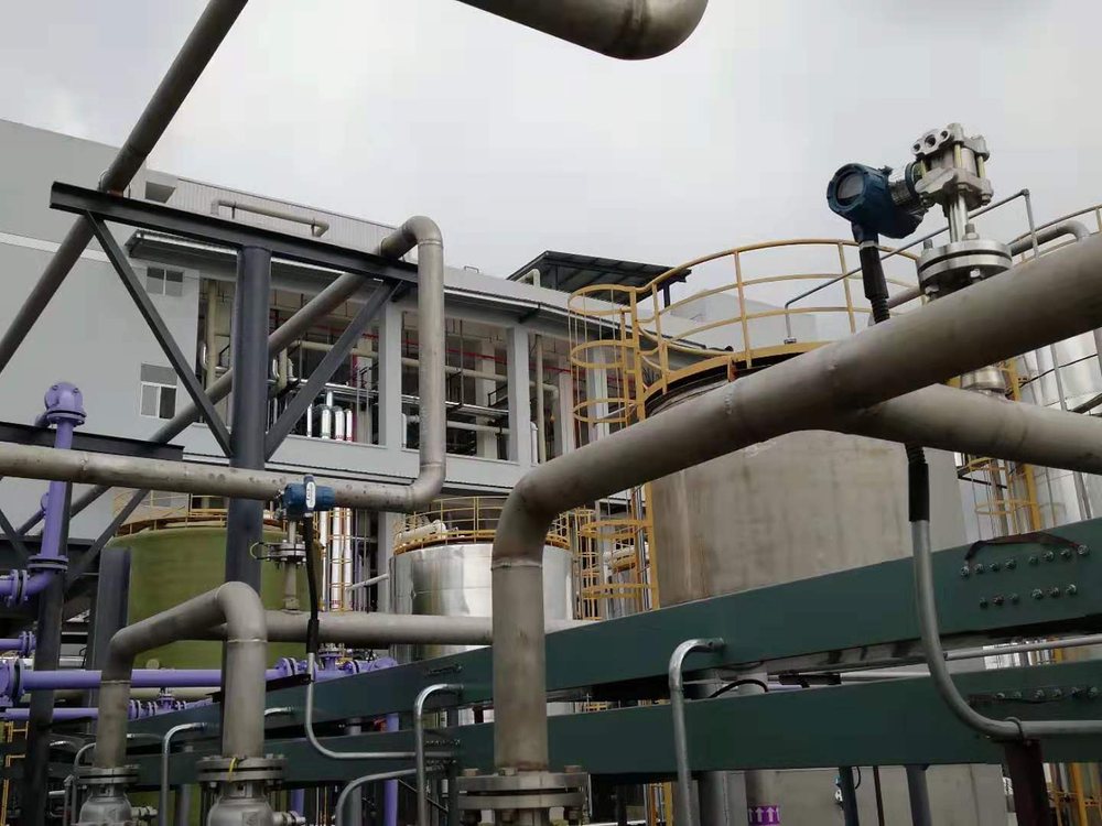
Oil and gas, Malaysia. A diesel storage tank needed continuous level over a 1 m range, at or below 10 psi and 60 °C, brought back as 4-20 mA. The tank offered one mounting point: a DN40 ANSI 150 raised-face flange. That fixes the probe diameter and the insertion length before any accuracy discussion starts. A flange-mounted magnetostrictive transmitter was proposed on that connection, with the option of a second float for the water interface. The mounting connection, not the accuracy class, shaped the selection.
Day tank alarm points
A generator day tank is a small tank next to the engine, kept full by a transfer pump drawing from the bulk tank. It is the tank most likely to be measured badly. It is small, it is refilled often, and the level signal is doing two jobs at once: telling an operator how much fuel is there, and driving the pump.
Separate those jobs. The continuous transmitter reports level and starts and stops the transfer pump. Give it a deadband wide enough that the pump is not short-cycling on every ripple. The high-level and low-level alarms should come from an independent switch rather than a second setpoint inside the same transmitter, because a transmitter that fails also fails its own alarm.
NFPA 110 ties the low-fuel alarm to the fuel volume the system class is required to hold. It also requires the transfer pump to be powered from the emergency supply. A Class 2 system, for instance, has to hold two hours of on-site fuel. Confirm the class, the required volume and the alarm points against the edition your authority having jurisdiction enforces, because those requirements change between editions.
Where the fill line discharges into the tank, the surface moves during a delivery, and any surface-following instrument moves with it. A stilling well quiets that without changing the measurement.
Hazardous area classification
Diesel with a flash point above 55 °C does not produce an ignitable vapor at normal ambient temperature the way gasoline does. A diesel tank is therefore classified less severely than a gasoline tank on many sites.
That is a statement about the fuel, not a permission slip. A tank that is heated, a tank that has held gasoline, and the area immediately around a vent or a fill point are all treated differently. The classification is set by the authority having jurisdiction and the site drawings, not by the instrument catalog.
What that means in practice is that the certification you specify follows the drawing. Where a classified area is called out, an intrinsically safe loop with a barrier and a two-wire transmitter is usually the cleaner answer than a flameproof enclosure, because it keeps the field wiring simple. Our guide to Class I Division 1 and Division 2 explains how those boundaries are drawn.
Checking against a dip
An instrument that has never been checked against a stick is an assumption. Verification on a fuel tank is not difficult and does not need a calibration laboratory.
Dip the tank with a gauge stick, with water-finding paste on the lower part of it, and read both the fuel depth and the water depth. Convert the dipped depth to volume with the tank chart, then compare that against what the instrument reports.
Do it at two different levels, not one, because a single point cannot separate a zero shift from a span error. A difference that stays constant across both levels is a zero problem, usually a density or a mounting height assumption. A difference that grows with level is a span problem.
Record what you find each time. A gauge that drifts a little every quarter is telling you something a single reading never will.
Choosing by tank
Selection on fuel tanks is decided by the tank far more often than by the specification sheet, and the first question is which opening is free.
| Tank and situation | Where to start |
|---|---|
| Generator day tank | A magnetostrictive transmitter on the top flange, with an independent float level switch for the alarms |
| Bulk aboveground tank | A radar level sensor for oil tanks where a clear vertical shot exists, or guided wave radar where it does not |
| Underground or buried tank | A submersible level transducer through the fill or dip pipe, with the fuel density set correctly |
| Only the vent or a small port free | A non-contact ultrasonic transmitter, allowing for its blanking distance below the roof |
| Local indication only | A magnetic level gauge, readable with no power at the tank |
Fuel inventory work usually ends up needing level and volume together rather than level alone. A diesel tank project in El Salvador ran exactly that way. It combined a submersible level sensor on the tank, a volume totalizing readout built on the tank chart, and a flow meter on the transfer line, proposed as one scheme rather than three separate instruments. If that is the shape of your problem, tell us the tank first. The full range is on the level instruments page.
Water tanks invert several of these constraints: the density term stops mattering and the compliance question takes over, which our water storage tank level sensor guide works through.
If the tank is buried rather than on a stand, start with the underground tank level guide for riser and EPA constraints.
Mineral insulating oil behaves much like diesel from a level-measurement standpoint; for the electrical-equipment side of oil level, read our guide to transformer oil level indicators.
Why a dielectric constant of 2.1 returns only 3.4 percent of the pulse, and what that means for the radar choice, is worked through in our dielectric constant and radar level measurement guide.
For a closer look at capacitive probes themselves, including output conventions and the water error arithmetic, see our capacitive fuel level sensor guide.
FAQ
How do you measure a diesel tank?
Either by dipping it with a gauge stick and converting the depth with the tank chart, or with a permanently installed instrument. The instrument options are a float or magnetostrictive probe through a top opening, a hydrostatic transmitter at the bottom, or a non-contact ultrasonic or radar sensor in the roof. Storage tanks normally use both, with the dip verifying the instrument.
How to measure fuel tank level?
Pick the technology from the opening the tank gives you and the depth you need to cover. A top opening the full depth of the tank favors magnetostrictive or guided wave radar. A bottom or side connection favors a hydrostatic transmitter with the fuel density set correctly. A roof opening with a clear shot at the surface favors radar. Then convert level to volume with a tank chart.
How can I check my oil tank without a gauge?
Dip it. A gauge stick, marked to the tank chart, gives the fuel depth directly. Water-finding paste on the bottom of the stick shows the water layer at the same time. It is also how you verify an installed gauge that you suspect is drifting.
How low should I let my diesel tank go?
On a storage tank the limit is set by what is at the bottom rather than by the pump. Water and sludge collect below the fuel, and drawing the level down toward the outlet pulls that material into the filters. Keep the working range above the bottom section, and manage the water by dipping and draining rather than by running the tank low.
Request a quote
Tell us the tank, the free opening and the fuel, and we configure one instrument for the application rather than a shelf part. Reach our application engineers or use the form below.
Written and technically reviewed by Wu Peng and the Instranova engineering team.