Flow Meters › Argon Flow Meter
Argon Flow Meter
An argon flow meter measures shielding gas to a TIG or MIG torch, purge gas to a weld root, or argon in a plant supply line. The welding versions are small variable area tubes; the plant versions are the same instruments scaled up, plus thermal mass and turbine meters. This page covers how to read, correct, and size both, not brand-by-brand shopping for regulator kits.
The reason the subject needs a page is that a gas flow tube only reads correctly under the conditions printed on it. Change the gas, change the inlet pressure, or read it at the bottom of its scale, and the error grows to tens of percent. Nothing on the instrument shows it. The corrections are simple square roots, and they are worked below with real numbers.
Beyond the weld cell, a flow meter for argon also serves furnace inerting, laser cutting assist gas, and bulk distribution, and those cases are covered below. For other gases, the industrial oxygen flow meter and compressed air flow meter pages follow the same logic for their own services.
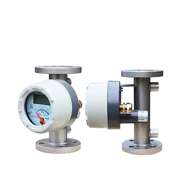 Metal Tube Rotameter
Variable area meter in stainless steel with local pointer or 4-20 mA; the industrial form of the welding flow tube.
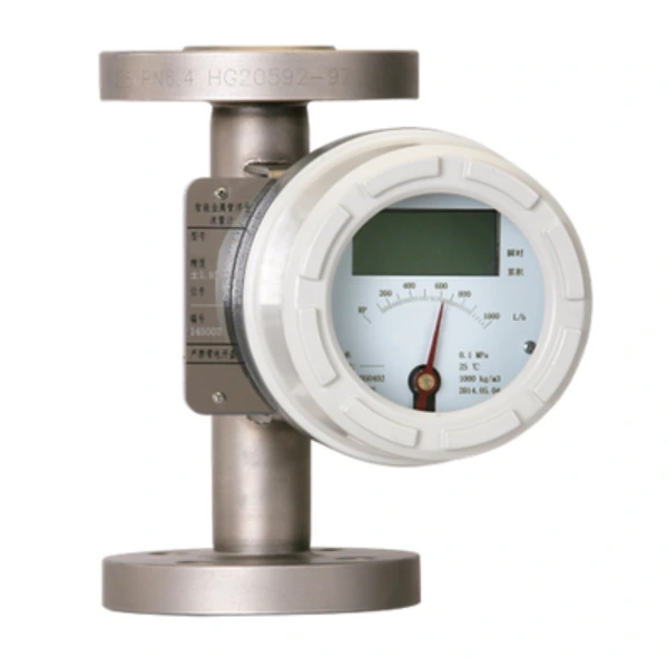 Gas Rotameter
Variable area meter with built-in temperature and pressure compensation, totalizing argon in standard volume.
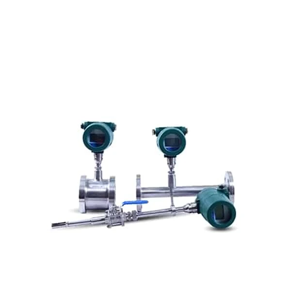 Thermal Mass Flow Meter
Reads argon mass flow directly with no temperature or pressure correction; the tool for manifolds and leak baselines.
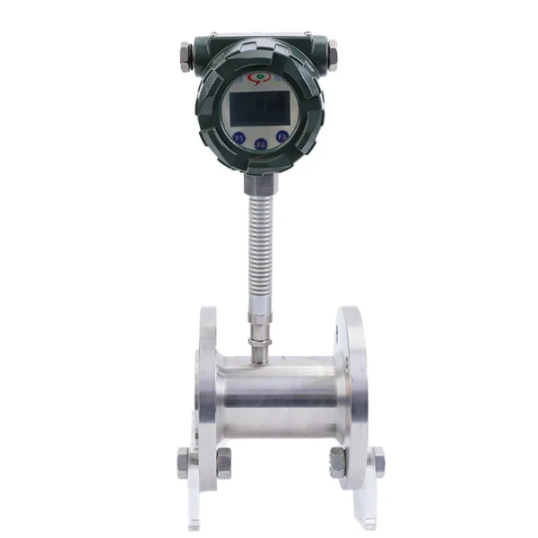 Cryogenic Turbine Flow Meter
For liquid argon between bulk tank and vaporizer, with a rotor and bearings rated for cryogenic service.
Flow meter or regulator
Three different devices get sold under one name, and the confusion costs gas. A regulator sets pressure.
A flowgauge regulator, often sold as an argon flow gauge, adds a second pressure gauge with a CFH scale printed on it. It infers flow from the pressure drop across a fixed orifice, which is an estimate, and a poor one at low settings. A true welding gas flow meter is the ball-in-tube type, a small variable area meter that measures the flow itself, with a needle valve to adjust it.
The division of labor matters: the regulator controls pressure, the valve controls flow, and the tube only indicates. On a combined flowmeter regulator, the regulator stage is factory-set to a fixed outlet pressure and the knob you turn is the needle valve. Set the flow with gas moving through the torch, after the initial surge settles. A reading taken with the line dead ended means nothing, because there is no flow to indicate.
Preset inlet pressure
Every ball-in-tube scale is drawn for one gas at one pressure. The float position depends on gas density, and density in the tube depends on pressure. So the maker fixes the pressure with a preset regulator stage and prints the scale for it. That is the entire reason welding flowmeters come preset, commonly at 50 psi in North America, with other lines built for 20, 30, or 80 psi.
Run the tube at the wrong pressure and the scale no longer applies. The correction is a square root of the absolute pressure ratio. A tube scaled at 50 psig but fed 30 psig delivers about √(44.7/64.7) = 0.83 of the indicated flow, so a float on the 20 CFH line is passing about 17 CFH.
The same physics is why a leak downstream of the tube reads as extra flow. The inlet pressure marked on the meter body belongs to the calibration, not to the installer’s preference.
Setting welding flow
Shielding flow scales with the nozzle, the joint, and the draft in the shop, which is why published numbers spread. The bands below sit inside the ranges welding references publish; treat them as starting points and adjust from bead appearance. Too little flow leaves porosity at the bead edges. Far too much creates a turbulent jet that pulls air into its own shield, so more is not safer past roughly the mid 30s CFH on common cups.
| Process | Typical setting | In L/min | Notes |
|---|---|---|---|
| TIG, small cup | 12 to 16 CFH | 6 to 8 | Gas lens allows the lower end |
| TIG, large cup | 18 to 25 CFH | 8 to 12 | Flow follows cup bore, not amperage |
| MIG, short circuit | 20 to 30 CFH | 9 to 14 | Larger nozzles and spray transfer run the top of the band |
| Overhead or drafty work | Add 3 to 5 CFH | Add 1.5 to 2.5 | Argon is denser than air and falls away from an overhead joint |
| Root purging | Set by volume exchanges | — | Purge to an oxygen level, then cut back to a holding flow |
The unit conversion trips more people than the settings do. One CFH is 0.472 L/min, so a procedure written at 12 L/min calls for about 25 CFH, and a 60 CFH tube tops out at 28.3 L/min. The flow rate units guide carries the full conversion set.
Gas correction factors
A variable area tube reads correctly only on the gas its scale was drawn for. On any other gas the float balances at a different height for the same flow. The fix is one line of arithmetic: multiply the indicated value by the square root of the ratio of molar masses, scale gas over actual gas. The factors below fall straight out of that rule.
| Scale drawn for | Gas in the tube | Multiply reading by | Meaning |
|---|---|---|---|
| Air | Argon | 0.85 | An air-scaled tube over-reads argon by about 17 percent |
| Air | CO2 | 0.81 | Over-reads CO2 by about 23 percent |
| Argon | 75/25 Ar-CO2 | 0.99 | Mixed gas on an argon scale is off by only about 1 percent |
| Argon | CO2 | 0.95 | Pure CO2 on an argon scale reads about 5 percent high |
| Argon | Helium | 3.16 | Helium needs its own scale; the argon reading is meaningless |
| Argon | Nitrogen | 1.19 | An argon tube passes about 19 percent more nitrogen than indicated |
This is why a dual-scale argon CO2 flow meter prints both scales side by side, and why helium always gets a separate tube or scale. It also answers a common shop question in one row. An argon flowmeter used on a nitrogen purge line delivers about 19 percent more than it indicates, which is safe for purging but wrong for records.
Accuracy at low flow
Small variable area meters are specified in percent of full scale, and that basis bites hardest at the settings welders use. A tube rated 5 percent of a 60 CFH full scale is allowed 3 CFH of error anywhere on the scale. At a 15 CFH TIG setting that is 20 percent of the reading, the difference between 12 and 18 CFH. The instrument cannot resolve the exact band where shielding starts to fail.
The practical answers are to buy the range that puts the working flow in the upper half of the scale, or to move up an instrument class. An industrial metal tube rotameter carries a 1.5 or 2.5 accuracy grade and can add a 4-20 mA output. A gas rotameter with temperature and pressure compensation removes the scale-condition corrections entirely by totalizing in standard volume.
Manifold and plant metering
Torch-side tubes answer one welder’s question; the plant question is where the argon bill goes. The arithmetic is worth writing out: 40 welding cells set to 25 CFH with the arc on 20 percent of the time average 200 CFH, about 5.7 m³/h, through the header. A thermal mass flow meter on that header reads the total in mass or standard volume with no pressure correction. One overnight reading answers the leak question: flow above zero with every torch idle is the leak rate, in numbers.
The same header data exposes surge waste. Each arc start dumps a burst of gas stored in the hose before the flow settles, so a shop full of short welds consumes measurably more per weld than its flowmeter settings suggest. Surge-restricting orifices at the feeder cut exactly that loss. For larger pipes and billing-grade totals, an ultrasonic gas flow meter covers the high end of the range.
Application example
Industrial gas lines, nitrogen and argon. An inquiry covered two gas lines: nitrogen at 1,000 L/min and argon at 200 L/min. Quoted: DN15 and DN25 metal tube rotameters with local indication of instantaneous flow plus a cumulative total, matching the request for a simple reading without data logging. Variable area metering suits fixed-rate inert gas lines where a visible local number is the requirement.
Liquid argon service
Above a few cylinders a day, argon arrives as liquid, and the metering point moves to the cryogenic side. Liquid argon boils at −186 C with a density near 1.4 kg/L, and one liter of liquid becomes roughly 840 liters of gas at room conditions. A small error at the liquid meter is a large error in the gas accounts. A welding-style tube has no place here.
Between bulk tank and vaporizer the job belongs to a cryogenic turbine flow meter with cold-rated bearings, or a Coriolis meter where the total must stand in kilograms. Downstream of the vaporizer, the gas is ordinary warm argon and the thermal mass and rotameter choices above apply unchanged.
FAQ
How does an argon flow meter work?
The ball-in-tube type is a variable area meter. Gas flows up through a tapered tube and lifts the float until the drag of the gas moving past it balances the float’s weight. The wider the tube gets, the more gas it takes to hold the float there, so float height maps to flow rate. It is drag holding the float up, not pressure, which is why the reading depends on gas density and why each scale is drawn for one gas at one inlet pressure.
What should argon flow rate be?
For TIG, use 12 to 16 CFH with a small cup and 18 to 25 CFH with a large one. For MIG on mixed gas, use 20 to 30 CFH, adding 3 to 5 CFH for overhead or drafty work. In metric terms those bands run about 6 to 14 L/min. More is not better: past the mid 30s CFH on common nozzles the jet turns turbulent and pulls air into the shield, producing the porosity the gas was meant to prevent.
What is the price of an argon gas flow meter?
Welding flowmeter regulators run from about 20 to 250 dollars depending on build and brand. Industrial panel-mount variable area meters for argon start around 400 dollars. Metal tube rotameters with transmitters and totalizers sit in the hundreds per point, and thermal mass meters for manifold metering are a four-figure instrument. The price steps track accuracy, materials, and signal output, and at the top end a change of measuring principle.
Can I MIG weld with 100% argon gas?
The gas will flow and the arc will run, but on carbon steel pure argon gives an erratic, undercut-prone bead with a narrow penetration profile. That is why steel MIG runs argon-CO2 mixes such as 75/25. Pure argon is standard for MIG on aluminum. At the meter the swap barely registers: 75/25 mix on an argon-scaled tube reads within about 1 percent, so no correction is needed when switching between them.
Request a quote
Tell us the gas, the flow range, the line pressure, and whether you need local indication, a 4-20 mA signal, or a standard-volume total. We size the tube or meter for argon directly, so no field correction factors are left for the operator.