By Wu Peng, Senior Process Instrumentation Engineer · Last reviewed July 29, 2026
There are eight standard thermocouple types, split into two families. The base metal types J, K, T, E and N cover roughly −200 to 1260 °C and handle most industrial work. The noble metal types S, R and B use platinum alloys and extend the range to 1700 °C. Type K is the industrial default; the others exist because K has limits that a specific alloy pair fixes.
The letters come with hard numbers attached: a defined temperature range, a tolerance class under IEC 60584 or ASTM E230, a millivolt output curve, and a wire color code. This page puts all of them in one place. You get the tolerance math both standards use, a Type K millivolt table with no PDF download, and the checks that identify an unmarked sensor.
Contents
- The eight types
- Comparison chart
- Tolerance classes
- Type K table
- Range caveats
- Wire color codes
- Identifying unknown types
- Choosing a type
- FAQ
The eight types
Every thermocouple works the same way: two dissimilar alloy wires joined at the hot end produce a small voltage that depends on temperature. What the type letter changes is the alloy pair, and with it the range, the output level, and the failure modes.
Among the base metals, Type K (nickel-chromium against nickel-aluminum, the pair sold as Chromel and Alumel) is the general purpose choice up to about 1100 °C in continuous service. Type J (iron against constantan) costs about the same. Its iron leg rusts and oxidizes quickly above 540 °C, so it stays in dry, sheltered service such as plastics machinery.
Type T (copper against constantan) is the low temperature specialist, stable and repeatable from −200 to 350 °C, common in food, pharma and cryogenic work. Type E (nickel-chromium against constantan) produces the highest output of any standard type, around 68 µV per °C, which helps low temperature resolution. Type N (Nicrosil against Nisil) was developed to remove Type K’s drift in the 300 to 600 °C band and its instability when cycled hot. It is the modern pick where K keeps drifting.
The noble metals trade output for reach. Type S (platinum-10% rhodium against platinum) and Type R (platinum-13% rhodium against platinum) run to 1600 °C and hold calibration well. S is the historical laboratory standard; R is the slightly higher output industrial twin.
Type B (platinum-30% rhodium against platinum-6% rhodium) reaches 1700 °C. Its output is negligible below about 50 °C, so reference junction errors near ambient barely register. Beyond the eight letter types, tungsten-rhenium pairs (Type C) reach about 2300 °C but survive only in inert or vacuum atmospheres.
Comparison chart
| Type | Legs (+ / −) | Range, °C | Typical service |
|---|---|---|---|
| K | NiCr / NiAl | −200 to 1260 | Industrial default |
| J | Fe / constantan | −40 to 750 | Plastics, dry service |
| T | Cu / constantan | −200 to 350 | Food, pharma, cryogenic |
| E | NiCr / constantan | −200 to 900 | Highest output; cryo to mid |
| N | Nicrosil / Nisil | −200 to 1300 | Drift resistant K upgrade |
| S | Pt-10Rh / Pt | 0 to 1600 | Laboratory, glass |
| R | Pt-13Rh / Pt | 0 to 1600 | Industrial high temperature |
| B | Pt-30Rh / Pt-6Rh | 600 to 1700 | Glass, top end furnaces |
| C | W-5Re / W-26Re | 0 to 2320 | Vacuum or inert only |
Ranges are typical published spans for sheathed industrial assemblies; bare wire reference tables extend further, and continuous service limits are lower still. See the range caveats below, and the tolerance classes for accuracy figures.
Tolerance classes
Two standards define how accurate a new thermocouple must be. IEC 60584-1 uses Class 1 and Class 2; ASTM E230 uses special limits and standard limits. Each tolerance is the greater of a fixed value in °C and a percentage of the measured temperature. It applies to new, unused wire; drift in service comes on top.
| Type | IEC Class 1 | IEC Class 2 | ASTM standard | ASTM special |
|---|---|---|---|---|
| K, N | ±1.5 °C or 0.4% | ±2.5 °C or 0.75% | ±2.2 °C or 0.75% | ±1.1 °C or 0.4% |
| J | ±1.5 °C or 0.4% | ±2.5 °C or 0.75% | ±2.2 °C or 0.75% | ±1.1 °C or 0.4% |
| T | ±0.5 °C or 0.4% | ±1.0 °C or 0.75% | ±1.0 °C or 0.75% | ±0.5 °C or 0.4% |
| E | ±1.5 °C or 0.4% | ±2.5 °C or 0.75% | ±1.7 °C or 0.5% | ±1.0 °C or 0.4% |
| R, S | ±1.0 °C to 1100 °C | ±1.5 °C or 0.25% | ±1.5 °C or 0.25% | ±0.6 °C or 0.1% |
| B | Not defined | 0.25% above 600 °C | ±0.5% | ±0.25% |
Percentages apply to the measured temperature in °C, and the greater value governs. IEC Class 1 validity ends at 1000 °C for K and N, 750 °C for J, and 800 °C for E. Above 1100 °C the R and S Class 1 limit grows by a formula. Values per IEC 60584-1 and ASTM E230.
Run the numbers once and the structure becomes clear. A Type K at 500 °C: IEC Class 1 allows the greater of 1.5 °C and 0.4% of 500 = 2.0, so ±2.0 °C. Class 2 allows the greater of 2.5 and 3.75, so ±3.75 °C. ASTM standard limits give the same ±3.75 °C, and ASTM special limits give ±2.0 °C.
At this temperature the two standards land in the same place; the fixed offsets only separate them near the bottom of the range. Whether that tolerance is enough depends on your error budget, which is a separate topic covered in our guide to accuracy vs precision.
Type K table
The reference table converts measured millivolts to temperature. The excerpt below is the IEC 60584-1 (ITS-90) function for Type K with the reference junction at 0 °C. The full table runs from −270 to 1372 °C in one degree steps; your transmitter or input card carries it internally.
| °C | mV | °C | mV |
|---|---|---|---|
| 0 | 0.000 | 700 | 29.129 |
| 100 | 4.096 | 800 | 33.275 |
| 200 | 8.138 | 900 | 37.326 |
| 300 | 12.209 | 1000 | 41.276 |
| 400 | 16.397 | 1100 | 45.119 |
| 500 | 20.644 | 1200 | 48.838 |
| 600 | 24.905 | 1300 | 52.410 |
Reference junction at 0 °C. Interpolate between rows for intermediate readings; the curve averages about 41 µV per °C from 0 to 1000 °C.
The table is also a bench tool. Read 20.6 mV on a millivolt meter across a Type K and the junction is near 500 °C. Read a value that disagrees with the process by a fixed few millivolts and you likely have the wrong reference junction handling, not a bad sensor.
The low signal level is why thermocouple wiring insists on matched extension cable while an RTD circuit tolerates plain copper. The two sensor families split the wiring problem very differently, as our RTD wiring guide shows.
Range caveats
Published range numbers for the same type disagree from one source to the next, and all of them are defensible because they measure different things. Three numbers matter, and they are not interchangeable.
The reference table range is where the mV function is defined; for Type K that is −270 to 1372 °C. The tolerance validity range is where the accuracy classes apply; Class 2 for Type K ends at 1200 °C. The continuous service limit is what the wire survives day after day; for a sheathed Type K that is closer to 1100 °C, and less for thin conductors.
Wire gauge moves the practical limit a long way. A heavy 8 AWG Type J pair survives temperatures that would destroy a 30 AWG pair in hours, and manufacturers publish derated limits for each gauge.
Atmosphere matters as much. In the 816 to 1038 °C band with scarce oxygen, Type K suffers a known failure called green rot: the chromium in the positive leg oxidizes preferentially and the output drifts low. Ventilated or purged protection tubes prevent it, or Type N sidesteps it.
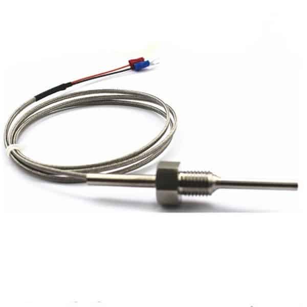
When you specify a sensor, quote the continuous operating temperature you need, not the table maximum, and let the supplier size the wire and sheath. That is exactly what the ordering codes on our thermocouple assemblies capture.
Wire color codes
Two color systems are in circulation, and they disagree on almost everything. Under ANSI MC96.1, used in North America, the negative lead is always red and the positive lead carries the type color. Under IEC 60584-3, used in most of the rest of the world, the negative lead is always white and the sheath carries the type color. A red lead therefore means opposite things under the two standards, which is a regular source of reversed-polarity hookups on imported equipment.
| Type | IEC 60584-3 (+ / − / sheath) | ANSI MC96.1 (+ / − / jacket) |
|---|---|---|
| K | Green / white / green | Yellow / red / yellow |
| J | Black / white / black | White / red / black |
| T | Brown / white / brown | Blue / red / blue |
| E | Violet / white / violet | Purple / red / purple |
| N | Pink / white / pink | Orange / red / orange |
| R, S | Orange / white / orange | Black / red / green |
| B | Copper leads common | Gray / red / gray |
Colors shown for extension and compensating cable. Older national schemes (DIN, BS, JIS) still appear on legacy plants; confirm against the cable marking.
Extension cable must match the thermocouple alloy, or a compensating alloy rated for the run. Splicing plain copper into a Type K circuit creates a second junction at the splice, and that junction feeds the ambient temperature into your reading as an offset of several degrees. Type B is the one exception in practice: its output below 50 °C is so small that copper connections at the head introduce almost nothing.
Identifying unknown types
An unmarked probe can usually be identified in a few minutes. Start with a magnet. The iron positive leg of a Type J is strongly magnetic, and the negative leg of a Type K, the aluminum-bearing alloy, is mildly magnetic. Platinum types are not magnetic at all.
Check the insulation colors against the table above, remembering which standard the plant buys to. Then confirm electrically: hold the junction at a known temperature and read the millivolts. A junction in boiling water at atmospheric pressure should read about 4.1 mV on a Type K; a reading near 5.3 mV points to Type J instead. Polarity falls out of the same test, since a reversed pair reads negative.
If the sensor lands on a transmitter or input card, the configured type must match the physical wire. A Type J sensor read as Type K produces a plausible looking value that is wrong by tens of degrees at process temperature. It is one of the most common commissioning faults in temperature loops.
Choosing a type
| Situation | Type to specify |
|---|---|
| Below 350 °C, tight tolerance | T, or consider an RTD for still better accuracy |
| General process to about 1100 °C | K, the default choice |
| K keeps drifting, or cycling above 1000 °C | N |
| 1100 to 1600 °C | S or R |
| 1600 to 1700 °C | B |
| Above 1700 °C, inert or vacuum | C, tungsten-rhenium |
Below about 600 °C the comparison that matters is not between thermocouple types but between a thermocouple and an RTD, which holds a tighter tolerance at the cost of range. Above that, the letter types take over.
Our thermocouple assemblies cover the base and noble metal types to IEC 60584, with the sheath, gauge and connection built to the service. A head mounted temperature transmitter converts the millivolt signal to 4-20 mA and handles the cold junction at the source. The wider measurement chain lives under temperature instruments.
Application example
Oil and gas, Pakistan. The customer needed high temperature process measurement over 0 to 1250 °C with a 1/2 inch NPT tapered thread and compression fitting, paired with a temperature transmitter. We proposed Type K assemblies to that specification, with the transmitters carrying the linearization and cold junction compensation.
When the decision is between a thermocouple and a platinum RTD rather than between thermocouple types, start with the RTD vs thermocouple guide.
Where those thermocouples feed a screen and a stored trend rather than a controller, the instrument doing it is covered in our guide to the paperless chart recorder.
For the physics behind these tables, see the plain-terms guide to what a thermocouple is and how it works. The K-specific range tiers, wire grades and drift mechanisms get a fuller treatment in the Type K thermocouple guide.
Two of these letter groups now have selection pages of their own: the base metal trio in our Type J, T and E guide, and the noble metals in the Type S, R and B guide.
Both current color charts, the legacy British and German codes, and the colors that mean different types under each standard are set out in our thermocouple color code guide.
FAQ
What is a type K thermocouple?
A Type K thermocouple pairs a nickel-chromium positive leg with a nickel-aluminum negative leg. It covers roughly −200 to 1260 °C, outputs about 41 µV per °C, and is the default industrial thermocouple because it is inexpensive, wide ranging, and accurate enough for most process work.
How do you determine the thermocouple type?
Check the lead and jacket colors against the ANSI or IEC code, test the legs with a magnet, and measure the millivolt output at a known temperature such as boiling water. About 4.1 mV at 100 °C indicates Type K; about 5.3 mV indicates Type J.
What is the difference between Type J and Type K thermocouples?
Type J uses an iron leg and stops at 750 °C; the iron corrodes in damp or oxidizing service. Type K uses nickel alloys, reaches 1260 °C, and tolerates open atmospheres better. Their tolerance classes are identical, so the choice comes down to temperature and environment, not accuracy.
Why are Type K thermocouples so popular?
Type K combines a very wide range, low cost, rugged nickel alloy legs, and universal instrument support; nearly every transmitter, PLC input and handheld meter carries its curve. Unless the application involves damp low temperature service, reducing atmospheres, or extreme precision, K is the safe default.
Request a quote
Tell us the application, the continuous operating temperature, and the atmosphere. We will configure the thermocouple type, sheath and gauge to match, and add a transmitter if the run back to the panel is long. Reach our application engineers or use the form below.
Written and technically reviewed by Wu Peng and the Instranova engineering team.