By Wu Peng, Senior Process Instrumentation Engineer · Last reviewed September 17, 2026
Type J, Type T and Type E are the three base metal thermocouples that sit below Type K in temperature. They sit above it in signal or in low-temperature behavior. A Type J thermocouple pairs iron with constantan and is tabulated by ASTM E230 from 0 to 760 °C.
A Type T thermocouple pairs copper with constantan and stops at 370 °C in air. Below zero it holds the tightest published tolerance of the three down to about −113 °C. A Type E thermocouple pairs chromel with constantan and gives 63.2 µV per °C over 0 to 100 °C, more output than any other standard letter type.
Many arguments about these three come down to a number that was copied without its basis. One vendor says Type T reaches 350 °C, the next says 370, a third says 400. All three are quoting real documents. This guide sets the ranges, tolerances, output, wire gauge limits and atmosphere rules side by side, and names the standard behind each number.
Contents
- Three base metal types
- Ranges by standard
- Tolerance classes compared
- Output and sensitivity
- Wire gauge limits
- Atmosphere and leg chemistry
- Color codes and cable
- Choosing between the three
- FAQ
Three base metal types
All three share the same negative leg. Constantan, a copper-nickel alloy, is the minus wire in J, T and E alike. What separates them is the positive leg: iron in J, copper in T, chromel in E.
That also explains where Type E gets its output. Chromel is the positive leg of a Type K and constantan is the negative leg of a Type T. Type E is built from the two halves that push hardest in opposite directions.
| Type | Positive leg | Negative leg | Magnet test |
|---|---|---|---|
| J | Iron | Constantan | Positive leg pulls strongly |
| T | Copper | Constantan | Neither leg responds |
| E | Chromel | Constantan | Neither leg responds |
Iron is the only ferromagnetic thermoelement among the three, which makes a pocket magnet a one-second sort for unmarked wire.
That magnet column is worth keeping. A strong pull on the positive wire means Type J. No response from either wire narrows the spool to T or E, and the copper color of the T positive leg separates those two by eye. For Type K the weak pull comes from the negative leg instead, covered in the Type K guide.
Ranges by standard
Published maximum temperatures for the same type differ from source to source: 350, 370 or 400 °C for Type T, and 800, 870 or 1000 °C for Type E. The numbers are not wrong. They come from three documents that stop in three different places.
The ASTM E230 tolerance table ends where the tolerance data ends. The IEC 60584-1 class ranges end where the class formulas end. The ITS-90 reference function is tabulated further than either.
| Type | ASTM E230 tolerance table | IEC 60584-1 classes | Numbers you will also see quoted |
|---|---|---|---|
| J | 0 to 760 °C | −40 to 750 °C | 700 continuous, 800 to 1000 short term; 1200, the end of the reference table |
| T | 0 to 370 °C, sub-zero row to −200 | −40 to 350, Class 3 to −200 | 400, the end of the reference table |
| E | 0 to 870 °C, sub-zero row to −200 | Class 1 to 800, Class 2 to 900 | 1000, the end of the reference table |
Every competing figure we found on supplier pages maps onto one of these three columns.
Read across the T row and the disagreement dissolves. The 350 is IEC, the 370 is ASTM, and the 400 is the last line of the ITS-90 table. A supplier quoting 400 °C is quoting a voltage that exists, at a temperature where no tolerance class applies and the copper leg is oxidizing in air.
The same reading applies to Type E. There, 1000 °C is a tabulated voltage and 870 is the last temperature with an ASTM tolerance behind it.
Tolerance classes compared
Both ASTM E230 and IEC 60584-1 state tolerance as a fixed value or a percentage of temperature, whichever is greater. That phrasing hides a crossover point. Below it the fixed value governs. Above it the percentage takes over and the error grows with every degree.
| Type | ASTM standard limits | IEC Class 1 | Crossover and top of range |
|---|---|---|---|
| J | ±2.2 °C or 0.75% | ±1.5 °C or 0.004t | ASTM turns at 293 °C, giving ±5.6 at 750; IEC turns at 375, giving ±3.0 |
| T | ±1.0 °C or 0.75% | ±0.5 °C or 0.004t | ASTM turns at 133 °C, giving ±2.6 at 350; IEC turns at 125, giving ±1.4 |
| E | ±1.7 °C or 0.5% | ±1.5 °C or 0.004t | ASTM turns at 340 °C, giving ±4.4 at 870; IEC turns at 375, giving ±3.2 at 800 |
Special limits of error tighten the ASTM figures above zero to ±1.1 or 0.4% for J, ±0.5 or 0.4% for T, and ±1.0 or 0.4% for E.
Two consequences follow. An IEC Class 1 element is tighter than an ASTM standard-limits element everywhere on these three curves, so a specification that names only a percentage is incomplete. The second consequence sits below zero, where the two documents part company.
ASTM E230 publishes sub-zero rows for two of the three: Type T at ±1.0 °C or 1.5% and Type E at ±1.7 °C or 1.0%, both from −200 to 0 °C. Type J has no sub-zero row at all. Neither carries a special grade, and the standard footnotes both as figures to agree with the supplier rather than as a class you can cite on its own.
IEC covers the cold differently: Class 1 and Class 2 start at −40 °C for all three types, and only Type T has a Class 3 that runs down to −200 °C. Run the two ASTM formulas and they cross. Type T is tighter from 0 °C down to about −113 °C, where its 1.5% term reaches the ±1.7 °C floor that Type E holds flat. Below that, Type E is tighter: ±2.0 °C at −200 °C against ±3.0 °C.
Cryogenic work therefore does not default to Type T on tolerance alone, so name the type, the grade and the standard edition on the purchase order.
Output and sensitivity
Output is the reason Type E exists at all. The ITS-90 reference functions give the voltage each pair produces against a 0 °C reference junction. Dividing by the temperature span gives an average sensitivity that can be compared directly.
| Type | mV at 100 °C | Average µV per °C, 0 to 100 | mV higher up |
|---|---|---|---|
| E | 6.319 | 63.2 | 37.005 at 500, 68.787 at 900 |
| J | 5.269 | 52.7 | 27.393 at 500, 42.281 at 750 |
| T | 4.279 | 42.8 | 17.819 at 350, 20.872 at 400 |
| K | 4.096 | 41.0 | 41.276 at 1000 |
Type K is listed for comparison. The same averages for all eight letter types are set out in our introduction to thermocouples.
Signal advantage of E over K = 6.319 / 4.096
6.319 / 4.096 = 1.543, so Type E delivers 54 percent more signal per degree than Type K over the same span.
Turn that into resolution. An input card that resolves 10 µV reads 0.16 °C of change on a Type E and 0.24 °C on a Type K. On a chamber holding a one-degree band, that is the difference between a reading that moves and a reading that sits still.
The same arithmetic explains why Type E suits long cable runs and electrically noisy plants. More millivolts per degree means induced interference counts for proportionally less.
Wire gauge limits
The letter type sets the ceiling of the alloy pair. The wire gauge sets the ceiling of the part on the order. Thin wire has less metal to lose before the conductor changes composition, so the service temperature of protected thermocouple wire falls as the gauge number rises.
| Wire size | Type J | Type E | Type T | Type K |
|---|---|---|---|---|
| 20 AWG | 480 °C | 540 °C | 260 °C | 980 °C |
| 24 and 28 AWG | 370 °C | 430 °C | 200 °C | 870 °C |
| 30 AWG | 320 °C | 370 °C | 150 °C | 760 °C |
Protected thermocouple wire. The Type K column is included so the gauge penalty can be compared with the coarser sizes listed in our Type K guide.
Go from 20 AWG to 30 AWG on a Type J and the usable temperature drops by 160 °C, from 480 to 320. Notice also that 20 AWG Type T is rated 260 °C, well under the 370 °C the tolerance table covers. The two numbers do not conflict: 370 is the top of the calibration table, 260 is the top of the wire you bought.
Atmosphere and leg chemistry
Each positive leg fails in a different way, and the failure mode is a better selection rule than the headline range. Iron oxidizes fast in air above roughly 540 °C. A Type J running at 700 °C in an oxidizing furnace will drift long before the tolerance table expires. The same iron rusts and embrittles at the other end, where condensation collects on a probe kept below ambient.
Copper oxidizes in air above about 370 °C, which is exactly where the Type T table stops. Chromel and constantan carry neither problem. Type E therefore holds up to 900 °C in oxidizing or inert conditions, but it is not recommended in vacuum or in partially oxidizing atmospheres.
| Condition | Type J | Type T | Type E |
|---|---|---|---|
| Oxidizing above 540 C | Iron oxidizes, heavy gauge only | Out of range | Suited, to 900 C |
| Reducing or vacuum | Suited, a common reason to pick J | Suited within range | Not recommended |
| Below 0 C, wet or damp | Rust and embrittlement | Moisture tolerant, tighter above −113 C | Usable, tighter below −113 C |
| Long cable or noisy plant | Middle output | Lowest output of the three | Highest output, best margin |
Color codes and cable
Two color systems are in circulation and they agree on very little. Under the ANSI system the negative wire is red on every type, and the positive wire carries the type color. Under IEC 60584-3 the negative wire is white on every type, and the sheath carries the type color.
| Type | ANSI positive | IEC sheath | Extension grade |
|---|---|---|---|
| J | White | Black | JX |
| T | Blue | Brown | TX |
| E | Purple | Violet | EX |
Under IEC 60584-3 the X suffix means extension grade, made from the same alloys as the sensor.
The X suffix matters more than it looks. JX, TX and EX cable is drawn from the same iron, copper, chromel and constantan as the element itself. What you give up by running extension cable is the narrower temperature band the cable is rated for, nothing else.
That is not true of every letter type. Type K also offers compensating grades built from substitute alloys, a distinction set out in the Type K wire guide. For J, T and E there is no substitute grade to get wrong. Polarity still is: reverse a pair and the panel reads the difference between the two ends rather than the process temperature.
Choosing between the three
Work down the constraints in this order and the choice usually makes itself. If any part of the measurement sits below 0 °C with moisture present, take Type T. Its legs do not rust, and down to about −113 °C it holds the tightest published sub-zero tolerance of the three. Below that, price Type E as well.
If the reading has to resolve fractions of a degree, or the cable run is long, take Type E for its 63.2 µV per °C. If the atmosphere is reducing, or the panel is already wired for it, Type J remains the straightforward answer. It is common on extruders and plastics machinery for that reason.
Above 760 °C none of the three apply, and the choice moves to Type K or Type N, covered in our thermocouple types chart. Past about 1200 °C the field narrows again to the platinum pairs in our Type S, R and B guide.
Application example
Industrial plant, India. An inquiry arrived for Type T beaded-junction thermocouples with no wire gauge stated. Gauge is the line in the table above that sets the service temperature, so rather than assume one we proposed the assembly with the gauge held open as a confirm-before-order item.
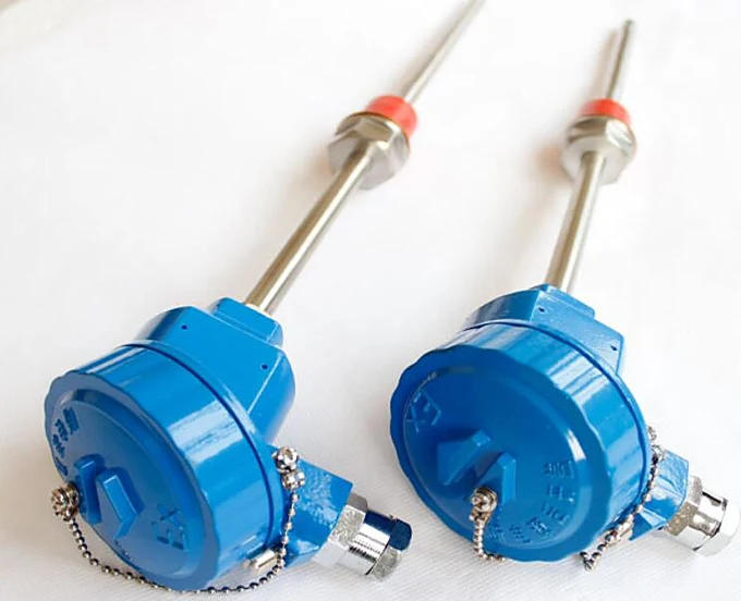
Once the letter type is settled, two decisions remain. A head-mounted temperature transmitter converts the millivolts to 4-20 mA at the sensor and removes the extension cable from the accuracy budget. A thermowell lets the element be replaced without opening the process.
If the application is clean, slow and below 600 °C, check a resistance sensor against the thermocouple before ordering. Our RTD and thermocouple comparison sets the two side by side. Finished assemblies are listed on the thermocouple sensor page.
If the cable in front of you was made to a different standard than the drawing assumes, our thermocouple color code guide compares the ANSI, IEC and legacy charts side by side.
For bench work on Type J and Type T signals, our millivolt to temperature converter runs the NIST conversion in both directions.
FAQ
What is type J thermocouple?
A Type J thermocouple is an iron and constantan pair. ASTM E230 tabulates it from 0 to 760 °C with standard limits of ±2.2 °C or 0.75%, and it produces 5.269 mV at 100 °C against a 0 °C reference. The iron positive leg makes it magnetic, suits it to reducing atmospheres, and rules it out of wet or sub-zero service.
What is the temperature range of a J type?
Three answers circulate and each has a basis. ASTM E230 tabulates tolerances to 760 °C, IEC 60584-1 runs its classes from −40 to 750 °C, and suppliers quote 700 °C continuous with short excursions to 800 °C or higher. The practical ceiling in air is lower still, because the iron leg oxidizes quickly above about 540 °C in fine gauges.
What is the difference between type T and type K thermocouples?
Type T is copper and constantan, tabulated by ASTM to 370 °C with a published sub-zero row to −200 °C. Type K is chromel and alumel and reaches 1260 °C. Type T is the more accurate and more moisture tolerant of the two in the cold, Type K is the only one of the pair that survives furnace temperatures.
What color is type T thermocouple wire?
Under the ANSI code the Type T positive wire is blue and the negative wire is red, with a blue overall jacket on extension grade. Under IEC 60584-3 the sheath is brown, the positive conductor is brown and the negative conductor is white. A blue jacket therefore means Type T in North America and nothing in particular elsewhere.
What is a Type E thermocouple cable?
Type E extension cable is designated EX and is drawn from the same chromel and constantan as the element, so it carries the signal without adding a junction error. It is rated over a narrower temperature band than the sensor itself. Purple identifies it under ANSI and violet under IEC 60584-3.
Request a quote
Tell us the application and we configure one unit, not a shelf part. Send the temperature range, the atmosphere, the insertion length and whether the element sits below zero, and we will come back with the letter type, the gauge and the tolerance class written into the specification. Reach our application engineers or use the form below.
Written and technically reviewed by Wu Peng and the Instranova engineering team.