By Wu Peng, Senior Process Instrumentation Engineer · Last reviewed September 29, 2026
Home › Tools › Thermocouple mV to Temperature Calculator
This thermocouple mV to temperature calculator works in both directions for Type K, Type J and Type T. Enter a measured millivolt value and the terminal temperature to get the hot junction temperature, or enter a temperature to get the millivolts a calibrator should source. Every result comes from the NIST reference functions. The math follows the rule the reference tables are built on: the meter reads E(Th) − E(Tref), so the reference junction EMF has to be added back before the table applies.
Published tables assume the reference junction sits at 0 °C. Real terminals sit at panel temperature, and with terminals above freezing, skipping that correction puts a Type K reading low by roughly the terminal temperature itself. Where the two junctions come from and why the EMF forms along the wires is covered in our thermocouple basics guide.
Calculator
Thermocouple mV and temperature converter
mV
Results update as you type. Conversions follow the NIST reference functions for Types K, J and T; the reference junction input accepts −50 to 150 °C. Verify safety-critical readings against a calibrated instrument.
Conversion method
Thermocouple voltage to temperature conversion always runs through the same two steps. First, add the EMF the reference junction would produce at its own temperature to the millivolts you measured: E(total) = V(measured) + E(Tref). Second, convert that total with the table or function for the type, which is defined against a 0 °C reference. Running the steps in the other order, or skipping the first one, is the classic mistake.
V(measured) = E(Th) − E(Tref), so Th = E⁻¹( V(measured) + E(Tref) )
A quick check you can type in now: the NIST table lists Type K at 100 °C as 4.096 mV against a 0 °C reference. Set the type to K, the reference junction to 0 °C and the measured value to 4.096, and the calculator returns 100.0 °C.
Temperature to voltage conversion, the calibrator direction, uses the NIST reference functions themselves, from the NIST thermocouple database (SRD 60), defined on the ITS-90 temperature scale. The reverse direction is harder, because the published inverse polynomials are curve fits with a small error of their own. NIST states the fit error for each range:
| Type | EMF range, mV | Temperature range, °C | Inverse fit error, °C |
|---|---|---|---|
| Type K | −5.891 to 0 | −200 to 0 | −0.02 to 0.04 |
| Type K | 0 to 20.644 | 0 to 500 | −0.05 to 0.04 |
| Type K | 20.644 to 54.886 | 500 to 1372 | −0.05 to 0.06 |
| Type J | −8.095 to 0 | −210 to 0 | −0.05 to 0.03 |
| Type J | 0 to 42.919 | 0 to 760 | −0.04 to 0.04 |
| Type J | 42.919 to 69.553 | 760 to 1200 | −0.04 to 0.03 |
| Type T | −5.603 to 0 | −200 to 0 | −0.02 to 0.04 |
| Type T | 0 to 20.872 | 0 to 400 | −0.03 to 0.03 |
This calculator uses the inverse fit only as a starting point, then refines the result against the direct reference function. The displayed temperature therefore reproduces the published tables to better than 0.01 °C, instead of carrying the fit error through. Below −200 °C the inverse fits stop. The working span here is −200 to 1372 °C for Type K, −210 to 1200 °C for Type J, and −200 to 400 °C for Type T.
Reference junction math
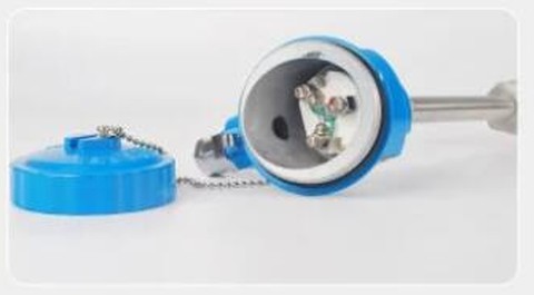
The reference junction correction is not a refinement. Near room temperature Type K changes by about 40 µV per °C, so every millivolt of reading stands for roughly 25 °C. Terminals at 24 °C subtract 0.960 mV from what the meter shows. Read the meter without adding that back and a 350 °C process reports as 327.0 °C, which is 23.0 °C low.
The correction also works below zero. Terminals on an outdoor rack at −5 °C produce −0.197 mV on Type K. The number added back is then negative, and the corrected total comes out smaller than the raw reading. The calculator accepts reference junctions from −50 to 150 °C in either °C or °F and handles the sign for you.
Transmitters and thermocouple input cards do all of this continuously: a small sensor at the terminal block measures Tref, and the electronics add E(Tref) before converting. A head-mounted temperature transmitter moves that terminal block to the sensor itself, which is why long thermocouple runs are often replaced by a transmitter and copper wire.
Checkpoint values
The rows below are NIST reference table values against a 0 °C reference junction, in mV. They are checkpoints for spot-checking a meter, a calibrator setting, or this page, not a full table. Complete tables and tolerance classes are in our thermocouple types guide, with per-type detail in the Type K guide and the Type J, T and E guide.
| Temp, °C | Type K, mV | Type J, mV | Type T, mV |
|---|---|---|---|
| −200 | −5.891 | −7.890 | −5.603 |
| −100 | −3.554 | −4.633 | −3.379 |
| 0 | 0.000 | 0.000 | 0.000 |
| 25 | 1.000 | 1.277 | 0.992 |
| 100 | 4.096 | 5.269 | 4.279 |
| 200 | 8.138 | 10.779 | 9.288 |
| 300 | 12.209 | 16.327 | 14.862 |
| 400 | 16.397 | 21.848 | 20.872 |
| 500 | 20.644 | 27.393 | above range |
| 600 | 24.905 | 33.102 | above range |
| 800 | 33.275 | 45.494 | above range |
| 1000 | 41.276 | 57.953 | above range |
| 1200 | 48.838 | 69.553 | above range |
| 1372 | 54.886 | above range | above range |
Type J is the odd one out at the cold end: its reference table starts at −210 °C, where it reads −8.095 mV. Type K and Type T tables continue down to −270 °C, but their inverse functions stop at −200 °C. This calculator stops there as well.
Worked example
A furnace zone runs on a Type K thermocouple. During troubleshooting, a technician lifts the wires at the panel and reads 13.333 mV with a millivolt meter. A separate probe puts the terminal block at 24 °C.
- Reference junction EMF at 24 °C, from the Type K function = 0.960 mV
- Total against a 0 °C reference: 13.333 + 0.960 = 14.293 mV
- Temperature from the NIST function = 350.0 °C
These are the default values in the calculator above, so it opens on this exact case. The same tool answers the calibration question in reverse. To make an instrument with 25 °C terminals display 300 °C on a Type J input, switch to the millivolts mode. It returns E(300) − E(25) = 16.327 − 1.277 = 15.050 mV to source.
Application note
Where this arithmetic shows up. None of the 330 inquiries in our order records asks for a millivolt conversion on its own. It rides along inside temperature jobs: a thermocouple assembly ordered with a transmitter that runs the conversion continuously, or a commissioning check on a sourced millivolt value. This page covers the bench and troubleshooting side of those jobs.
Related guides and tools
For what the two junctions are and why the EMF forms along the wires rather than at the tip, start with what a thermocouple is and how it works. The thermocouple testing guide puts these millivolt checks into a full fault-finding sequence, including resistance checks and fault limits.
Selection and wiring live in their own guides. Our color code guide identifies an unmarked pair, and the extension and compensating wire guide covers what happens to the reference junction when the run is extended. On the product side, our thermocouple assemblies and temperature transmitters pair the sensor with electronics that handle the conversion and the reference junction automatically.
FAQ
How to convert thermocouple millivolts to temperature?
Add the reference junction EMF to the measured millivolts, then look the total up in the table for that thermocouple type. Example for Type K with the terminals at 24 degrees C: the meter reads 13.333 millivolts and the reference junction contributes 0.960 millivolts. The total of 14.293 millivolts converts to 350 degrees C in the NIST table. The calculator on this page runs both steps for Types K, J and T.
How many mV should a thermocouple have?
It depends on the type and the temperature difference. Type K spans minus 5.891 to 54.886 millivolts over minus 200 to 1372 degrees C. Type J spans minus 8.095 to 69.553 millivolts and Type T spans minus 5.603 to 20.872 millivolts, both against a 0 degree C reference. Near room temperature the signal is small: Type K produces about 1 millivolt at 25 degrees C.
How to measure temperature from thermocouple?
Disconnect the loop, read the EMF at the terminals with a millivolt meter, and note the terminal temperature at the same time. Convert the reading with the reference junction included, as this page does. In a permanent installation a temperature transmitter or input card runs the same conversion continuously using its own reference junction sensor.
How does a thermocouple generate a voltage related to temperature?
The EMF develops along the length of each wire wherever it passes through a temperature gradient, not at the welded junction itself. Two dissimilar wires build up different EMFs over the same gradient, and the instrument reads the difference between them. The NIST reference functions define that relationship for each letter type.
Request a quote
If the conversion work points to new sensors, a transmitter, or a calibration source, tell us the type, temperature range and process connection. Reach our application engineers or use the form below.
Written and technically reviewed by Wu Peng and the Instranova engineering team.