By Wu Peng, Senior Process Instrumentation Engineer · Last reviewed September 14, 2026
The short version of HART vs Modbus: HART rides on the 4-20 mA loop you already have and adds a slow digital channel for configuration and diagnostics. Modbus replaces the analog signal with a digital bus that needs its own pair of wires and its own power. Plain 4-20 mA is the third option, and on most single-variable loops it is still the right one.
The choice takes one line on the purchase order. It then decides the input card, the cable, the power supply and the commissioning tools for the life of the loop. This guide puts the three outputs side by side at the specification level, works out what the receiving end must have, and does the update rate and distance arithmetic properly. It ends with three spec lines you can copy.
HART physics gets its own treatment in the HART communication protocol guide; this page is about choosing.
Contents
- Three outputs one decision
- Side by side
- What the host needs
- Power and wiring
- Update rate arithmetic
- Distance and loop limits
- Modbus setup pitfalls
- Gateways and fieldbus
- Writing the spec line
- FAQ
Three outputs one decision
A 4-20 mA output carries one process variable as a current. The receiving card converts the current to a number, and that is all that passes between them. Two conductors, one value, no addresses, no baud rate, no configuration file. That is why the loop is so hard to break.
HART keeps that current and superimposes a small frequency shift keyed tone on top of it. The analog value still reaches the control system the old way. A HART host can also read the other device variables, the tag, the range and the diagnostics, and can write configuration back.
The digital channel runs at 1200 bits per second because it was built to fit under an analog signal without disturbing it. The tone averages to zero, so a card that does not understand HART just sees the current.
Modbus is a different arrangement altogether. The instrument becomes a slave on a serial bus (Modbus RTU over RS-485) or on Ethernet (Modbus TCP), and the master reads registers. There is no analog value unless the instrument also carries a separate 4-20 mA output.
Everything the device measures is available as registers, several devices share one cable, and the bus is far faster than HART. In exchange the instrument usually needs its own power supply and the master needs a serial port or a gateway. Every device also needs an address, a baud rate, a parity setting and a register map that match the master.
Side by side
The table is written the way a specification reads, not the way a protocol tutorial reads. The numbers are the published limits from the HART Application Guide, the Modbus over Serial Line specification and the TIA-485 application notes. The conditions attached to each number are in the sections that follow.
| Item | 4-20 mA | 4-20 mA + HART | Modbus RTU (RS-485) |
|---|---|---|---|
| Signal | One variable as current | Same current plus FSK digital at 1200 bps | Digital only, 19200 bps default, 9600 common, up to 115200 |
| Wires to instrument | 2 (power and signal) | 2 (power and signal) | 2 data plus 2 power, often plus shield or common |
| Power | Loop powered, under 22 mA | Loop powered, under 22 mA | Separate supply; a Modbus mag meter transmitter draws watts, not a fraction of one |
| Devices per cable | 1 | 1 point to point; 15 (HART 5); addresses 1 to 63 in HART 7, quoted as 62 devices in the Application Guide; multidrop with current parked at 4 mA | 32 unit loads without a repeater; addresses 1 to 247 |
| Update | Continuous; set by transmitter damping and card scan | 2 to 3 digital reads per second, 3 to 4 in burst mode; analog value still continuous | Tens of milliseconds per poll at 19200 bps |
| Cable length | Set by the loop resistance budget; kilometers on 18 AWG | Set by cable capacitance; 3000 m theoretical, about 700 m with 15 devices on 70 pF/ft cable | 1000 m at 9600 bps on 26 AWG or heavier per the Modbus serial spec |
| Receiver | Any analog input | Any analog input for the current; HART input card, multiplexer or handheld for the digital side; 230 ohm minimum in the loop | Serial port or RS-485 card configured as master, or a serial to Ethernet gateway |
| Configuration | Range and units on the card | Tag, range, damping and variables written over the loop | Address, baud, parity, stop bits, register map and float byte order on both ends |
| Fault signaling | NAMUR NE43: 3.6 mA or less, 21 mA or more | NE43 current plus status bytes in every reply | Status registers and exception codes; a silent slave is a timeout |
Modbus TCP uses the same register model over Ethernet on TCP port 502, with a 7 byte MBAP header in front of each frame. Copper segments follow the usual 100 m Ethernet rule. Device counts, cable lengths and baud rates are limits, not targets.
What the host needs
Most mismatches I see are on the receiving side, not in the instrument. The transmitter is ordered with HART, the panel has a plain analog card, and the digital side is never used. The current still works, but the option was paid for and gives nothing.
The reverse is worse. A Modbus output specified for a panel with no serial master and no gateway cannot be read at all until someone buys more equipment.
| Receiving equipment | What it gets from each output |
|---|---|
| Plain analog input card | 4-20 mA: the value. HART: the value only; the tone averages to zero and is ignored. Modbus: nothing. |
| HART enabled input card | The value plus the secondary variables, status and configuration access, one channel per loop, with the sense resistor built in. |
| HART multiplexer or gateway | Digital access to many loops through one device management link, while the analog cards keep reading the current. |
| Handheld communicator | Configuration and diagnostics, clipped across the transmitter terminals or the sense resistor, with the loop still running. No permanent digital data path. |
| RS-485 serial master | Modbus RTU registers from every slave on the bus, one poll at a time. Reads 4-20 mA and HART loops only through a separate analog card. |
| Ethernet only host | Modbus TCP natively; Modbus RTU through a serial gateway; HART data through a HART-IP gateway or multiplexer. |
One number decides whether HART works on an existing analog card. The HART Application Guide requires at least 230 ohm of loop impedance, 250 ohm being typical. The FSK current has to develop a voltage that a modem can read, and the resistor is what develops it.
Current input channels vary widely here. One controller vendor builds its current inputs at 249 ohm, which is enough on its own. Another builds its current input at 25 ohm, far below the floor. On that card the loop reads fine as 4-20 mA, and HART does not answer until a 250 ohm resistor goes in series.
Check the card’s input impedance before deciding that a loop is HART ready. The same resistor enters the loop voltage budget. At 20 mA it drops 5.0 V, which the supply must cover before the transmitter gets its share.
Power and wiring
The two-wire loop is the main practical advantage of both 4-20 mA and HART. The instrument draws all of its power from the pair that carries the signal, never more than about 22 mA. One 24 VDC supply in the panel runs the loop, and an intrinsic safety barrier, if there is one, sits in the same two conductors. Adding HART changes nothing about the wiring; the two-wire, three-wire and four-wire arrangements are the same with or without the digital layer.
A Modbus instrument is normally a separately powered device. The RS-485 pair carries data only, and the electronics take their power from a second pair or from mains. One manufacturer’s published example is a magnetic flow meter transmitter with a Modbus output, rated for 12 to 42 VDC at 15 W or for 90 to 250 VAC.
That is a different order of magnitude from a loop that lives on half a watt. It changes the cable count and the supply sizing. In a hazardous area it changes the entire protection concept, since a 15 W device is not a candidate for a simple intrinsic safety barrier.
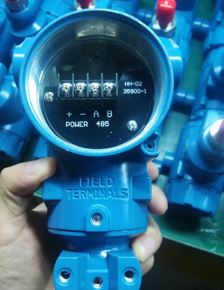
The RS-485 bus itself is a daisy chain, not a star. The Modbus serial specification calls for a termination at each end of the trunk: 150 ohm, or 120 ohm with a 1 nF capacitor in series. It also calls for a pair of polarization resistors between 450 and 650 ohm at one point on the bus, so the idle line sits at a defined level. Each polarization set costs four devices of the 32 device budget.
None of this exists on a current loop. It is easy to leave out when a Modbus instrument is wired by someone used to 4-20 mA.
Update rate arithmetic
The comparisons we read all say HART is slow and Modbus is faster. Only one attempts the arithmetic, and it gets the bit count wrong. It forgets that both protocols frame each byte in eleven bits, not eight: a start bit, eight data bits, a parity bit and a stop bit. That framing sets the real throughput.
Characters per second = baud rate / 11
HART: 1200 / 11 = 109 characters per second. Modbus RTU at 19200: 19200 / 11 = 1745 characters per second.
A HART command 1 exchange that returns the primary variable is a 14 byte request and a 21 byte response in long frame format, 35 bytes in all. At 109 characters per second the wire time is 321 ms before the turnaround between master and slave is added. That is why the HART Application Guide quotes 2 to 3 updates per second.
Ask for all four device variables with command 3 and the response grows to 40 bytes, 54 in total, about 495 ms on the wire. Poll 15 multidropped devices for four variables each and one scan of the segment takes roughly 7 to 8 seconds. That is fine for tank inventory and useless for a control loop, which is why multidrop HART is a monitoring arrangement, not a control one.
The same read on Modbus RTU is an 8 byte request and a 9 byte response for one floating point value in two registers, 17 bytes. At 19200 bps that is 9.7 ms on the wire. Add the mandatory 3.5 character silence at each end, about 2 ms each, and the slave’s own response delay, commonly set around 10 ms. Call it 25 ms per device, so thirty devices are scanned in under a second.
At 9600 bps the wire time doubles, the per device total is roughly 35 ms, and the scan is still close to one second.
The analog current has no update rate at all. The card samples it every few milliseconds, and the transmitter damping setting, not the wire, decides how fast the value can move.
Distance and loop limits
Three outputs, three different things that limit the cable run. For 4-20 mA it is resistance.
The supply voltage minus the transmitter’s minimum operating voltage, divided by 20 mA, is the total resistance the loop can carry. With a 24 V supply and a transmitter that needs 12 V, that is 600 ohm. Take away the 250 ohm sense resistor and 350 ohm is left for the cable.
On 18 AWG at 20.9 ohm per kilometer per conductor, 41.8 ohm per kilometer for the pair, 350 ohm is about 8 km. On 20 AWG at 33.2 ohm per kilometer per conductor it is about 5 km. Few plants get near either figure, which is why distance rarely decides against 4-20 mA. The current loop guide covers the budget in more detail.
For HART it is capacitance, not resistance, because the FSK tone has to keep its shape. The HART Application Guide gives a 3,000 m theoretical limit and then a table. On 18 AWG shielded pair at 20 pF/ft a single device can be 9,000 ft away, about 2,700 m. Fifteen multidropped devices on 70 pF/ft cable are limited to 2,300 ft, about 700 m.
The rule behind the table is that loop resistance multiplied by total capacitance must stay under 65 microseconds. Long runs on high capacitance cable are where HART stops answering while the 4-20 mA on the same pair keeps working.
For RS-485 it is the baud rate and the driver. The Modbus serial specification allows 1000 m at 9600 bps on 26 AWG or heavier. The TIA-485 application notes give about 4,000 ft, roughly 1,200 m, at 100 kbps on 22 AWG, and higher speeds shorten it. Modbus TCP inherits the Ethernet copper rule of about 100 m per segment and then goes as far as switches and fiber take it.
A remote well or a far tank is usually a 4-20 mA loop for exactly this reason: no bus limits, no terminations, one pair.
Modbus setup pitfalls
A current loop is commissioned by ranging the card. A Modbus link is commissioned by making at least six settings agree at both ends. Any one of them wrong looks identical from the master: a timeout. These are the ones that come up on instruments, taken from published transmitter manuals rather than from the protocol textbook.
| Setting | What goes wrong |
|---|---|
| Slave address | Valid range 1 to 247, 0 is broadcast. Two devices shipped at the default address 1 on one bus answer together and corrupt each other. |
| Register offset | Some masters count registers from 0, some from 1, and some manuals print 40001 while the wire carries 0. Reading the neighbor register gives a plausible wrong number, not an error. |
| Framing | The Modbus specification default is 8 data bits, even parity, one stop bit, at 19200 bps. Many masters default to no parity at 9600. If no parity is chosen the specification requires two stop bits. |
| Float byte order | A 32 bit value spans two 16 bit registers and transmitter manuals offer up to four byte orders. The wrong one produces a number that is not obviously broken, such as a flow of 2.6e+20. |
| Termination and bias | Missing terminations work on the bench and fail on the long run. A bus with no polarization floats between frames and the first character of some replies is lost. |
| Response delay | Slaves have a configurable minimum response delay, 10 ms being a common default. A master timeout set shorter than that plus the wire time sees every reply as late. |
None of these are hard, and all of them are invisible on the drawing. Ask for them on the instrument data sheet before ordering: default address, default baud and parity, the register map with data types, and the byte order. A Modbus instrument without those four items is not ready to integrate.
Gateways and fieldbus
The HART to Modbus gateway question comes up whenever a plant with HART instruments needs the diagnostics in a SCADA system that only speaks Modbus. The gateway, sometimes sold as a HART multiplexer or concentrator, polls each HART device and presents a fixed set of registers to the Modbus master. Those registers hold the primary through quaternary variable, the loop current and the device status. It does not map the entire HART command set, because a full mapping for a few dozen devices would run to thousands of registers.
Configuration and the deeper diagnostics still go to a HART host, usually through a pass-through mode on the same link. On some gateways the Modbus side is read only by design. Plan on one gateway feeding a handful of loops, and remember that a multidropped segment of 15 devices still scans in seconds, not milliseconds.
Fieldbus vs HART is a different comparison and mostly a historical one for new small projects. FOUNDATION Fieldbus H1 and PROFIBUS PA run a 31.25 kbit/s digital bus that also powers the instruments. They combine the two-wire economy of a loop with a fully digital signal, but they demand segment design, power conditioners and host support that most brownfield sites do not have.
If your host already has an H1 or PA segment, use it. If not, the practical choice for a new instrument is the three outputs on this page.
Application example
Municipal water, Chile. A utility needed flow on a DN200 groundwater line at a discharge point rated up to 10 bar, with the transmitter mounted away from the pipe. We quoted an insertion magnetic flow meter in remote mount form, 24 VDC powered, with an RS-485 Modbus RTU output. Modbus fits this arrangement better than a loop: the transmitter has its own supply, the remote mount already needs a multi-conductor cable, and one register read returns flow, totals and status together.
Writing the spec line
The output line on a purchase order is where HART protocol vs Modbus stops being a debate and becomes a part number. Three example lines, each complete enough that the supplier cannot guess wrong:
| Case | Spec line to write |
|---|---|
| Single control loop, existing analog card | Output 4-20 mA, two-wire loop powered, 24 VDC nominal, NAMUR NE43 fault current, range 0 to X in Y units. |
| Same loop, diagnostics wanted, HART host or handheld available | Output 4-20 mA with HART 7, two-wire loop powered, 24 VDC, minimum 250 ohm loop load confirmed at the input card, polling address 0. |
| Several variables or several meters to one SCADA port | Output RS-485 Modbus RTU, separately powered 24 VDC, address N, 19200 bps 8E1, register map and float byte order per data sheet, terminations by installer. |
Two rules cover most of the remaining cases. If the value goes into a control loop, specify 4-20 mA and add HART when the plant has a way to use it. If the value goes into a log, a totalizer or a SCADA screen, and the instrument is separately powered anyway, Modbus saves an analog channel per variable. It returns the totals as well.
Where both are needed, many instruments carry more than one port. Our magnetic flow meters are ordered with 4-20 mA, pulse and RS-485 together. Our HART pressure transmitters pair the loop with the digital layer, and a Modbus ultrasonic water meter adds M-Bus for billing networks.
A signal splitter handles the case where one current has to feed two systems. The 4-20 mA calculator converts between current and engineering value when you check a reading by hand.
FAQ
What is the difference between HART and Modbus?
HART is a digital signal added on top of a 4-20 mA loop at 1200 bps; the analog value keeps working and the digital side carries configuration and secondary variables. Modbus is a purely digital master and slave protocol on RS-485 or Ethernet that reads registers from many devices on one cable and needs the instrument to be separately powered.
Is HART an analog or digital protocol?
Both, by design. The 4-20 mA current is analog and carries the primary variable continuously; the HART tone superimposed on it is digital, two frequencies at 1200 bps that average to zero so the analog reading is not disturbed. A plain analog input card reads the current and never notices the digital layer.
Is HART an open protocol?
Yes. The specification is maintained by FieldComm Group and is available to any manufacturer, and HART devices from different vendors interoperate at the universal command level. Device specific commands still need the device description file from the manufacturer loaded in the host, which is the same situation Modbus is in with its register maps.
Why use HART protocol?
Because it adds diagnostics, remote configuration and three extra variables to a loop without touching the wiring, the input card or the power supply. A plant with hundreds of 4-20 mA loops can gain digital access one loop at a time with a handheld or a multiplexer, which no bus protocol can offer on the existing cable.
Which output should I specify: 4-20 mA, HART or Modbus?
Specify 4-20 mA for a value that feeds a control loop, and add HART when the host or a handheld can use it and the card presents at least 230 ohm. Specify Modbus RTU when the instrument is separately powered, several variables or several meters must reach one serial or SCADA port, and the master is confirmed to exist.
Request a quote
Tell us the host you have, the number of loops, the cable run and the variables you need. We configure the output to match the panel rather than the other way round. Reach our application engineers or use the form below.
Written and technically reviewed by Wu Peng and the Instranova engineering team.