By Wu Peng, Senior Process Instrumentation Engineer · Last reviewed August 17, 2026
Underground tank level is measured either continuously, with a submersible hydrostatic sensor, a magnetostrictive probe or a radar aimed down the riser, or manually with a marked gauge stick through the fill opening. Water and chemical tanks can take whichever method fits the opening. Fuel tanks in the US also answer to EPA release-detection rules, which shape what the instrument must do.
This guide covers buried water cisterns, fuel storage and chemical sumps. It does not cover the groundwater table itself; measuring water standing in a well is a different job, handled by a deep well water level sensor.
Contents
- The buried tank problem
- Sensor options compared
- Water tanks and cisterns
- Fuel tanks and ATG
- Measuring through the riser
- Level to volume
- Buried installation rules
- FAQ
The buried tank problem
A buried tank hides everything an above-ground installation shows you. There is no shell to clamp onto, no side nozzle to tap, and usually no way to see the liquid. Every instrument, and every repair, goes through one manhole or a riser pipe a few inches wide.
The environment underground is also harder on electronics than the tank farm above it. The manhole sump runs at near 100 percent humidity. The first meter of cable cycles between wet soil and air. Lightning surges travel farther along buried services than most sites expect.
Two more things separate buried service from a simple vertical tank. Most buried tanks are horizontal cylinders, so equal level changes do not mean equal volume changes. And if the tank holds fuel, the measurement doubles as leak detection, with federal numbers attached.
Sensor options compared
Five approaches cover nearly every buried tank. The table compares them on the constraints that matter underground: what fits through the opening, what the reading is based on, and what fails first.
| Method | How it reads a buried tank | Watch for |
|---|---|---|
| Submersible hydrostatic | Probe rests on the tank bottom and reads head pressure; drops through any 2 inch opening; see the submersible pressure transducer | Vent tube must stay dry; span follows liquid density |
| Magnetostrictive probe | Rigid probe down the riser with floats for product and water; the fuel-site standard; see the magnetostrictive level transmitter | Probe length must match tank depth; floats need periodic checks |
| Radar down the riser | Non-contact pulse from the manhole; nothing in the liquid; see the radar level transmitter | Riser geometry rules below; needs a smooth pipe |
| Ultrasonic | Acoustic pulse from the top of the riser or inside the tank crown | Blind zone of 0.25 to 0.5 m near the transducer; narrow risers ring |
| Gauge stick or dip tape | Manual reference reading through the fill pipe; still how sensors are sanity-checked | EPA requires markings to the nearest one-eighth inch on fuel tanks |
Float switches add low-cost point alarms on any of these. A tank sitting in an accessible vault, rather than backfilled soil, can also use an external clamp-on ultrasonic sensor on the exposed shell.
Water tanks and cisterns
For a buried water tank the reliable default is a submersible hydrostatic sensor on the tank floor, wired to a panel display or telemetry unit. The physics is one line:
P = ρ × g × h
2 m of water = 998 × 9.807 × 2 = 19.6 kPa, so a 0 to 25 kPa sensor covers a 2.5 m cistern with margin
One specification decides long-term accuracy: the pressure reference. A vented, gauge-reference sensor compares tank pressure against the atmosphere through a hollow tube in its cable, so weather changes cancel out.
A sealed absolute sensor does not. Ordinary barometric swings of plus or minus 3 kPa move its reading by about 0.31 m of water, a 12 percent error on a 2.5 m tank. The full mechanism is covered in our hydrostatic pressure guide.
For a one-off check, a clean dip stick or a weighted tape through the fill opening settles the question in a minute. A sensor is worth fitting when you want the reading at the house, a pump interlock or a low-level alarm. Above-ground storage is a different selection problem, covered in the water storage tank sensor guide. Our hydrostatic level sensors page lists the submersible line.
Fuel tanks and ATG
On a US fuel tank the level system is also the leak detector, and the EPA writes the pass marks. An automatic tank gauge is almost always a magnetostrictive probe with a product float and a water float. Its monthly test must detect a leak of 0.2 gallon per hour. Manual methods are allowed only on small tanks, and only by the book.
| EPA rule point | What it says |
|---|---|
| ATG leak test | Detect 0.2 gal/h in the monthly test; 0.1 gal/h models exist; tank must sit quiet before and during the test |
| Gauge stick | Marked to the nearest one-eighth of an inch; product-finding paste shows the wetted line |
| Manual tank gauging | Sole method for life only up to 1,000 gallons; not allowed above 2,000 gallons; weekly test keeps the tank undisturbed 36 hours or more |
| Water checks | Check for water in the tank bottom at least monthly; ethanol-blend fuels may not form a water bottom at all |
| Newer tanks | USTs installed or replaced after April 11, 2016 need secondary containment with interstitial monitoring; an ATG alone is no longer the primary release detection |
Summarized from the US EPA release detection pages for underground storage tanks; state programs can be stricter.
The water float is there because water sits under fuel and corrodes the tank from the inside while contaminating the product. A probe that reports product level, water level and temperature in one shaft is why magnetostrictive owns this application. Gauge selection on the diesel side, above and below grade, is covered in the diesel tank level gauge guide.
Measuring through the riser
The riser pipe decides which non-contact instruments can work. A radar shooting down a pipe is not free-space measurement anymore; the pipe behaves as a waveguide. It works well when the pipe is smooth metal, constant diameter, at least 2 inches, and the antenna is matched closely to the pipe bore.
Ultrasonic transmitters carry a second constraint: a blind zone of roughly 0.25 to 0.5 m in front of the transducer, where echoes cannot be evaluated. A sensor mounted at the top of a short riser can have its blind zone reach into the highest product levels. That caps how full the tank can read.
This is the practical reason contact probes dominate buried tanks. A magnetostrictive shaft or a submersible sensor on a cable passes through a 2 inch opening with no acoustics to manage. It reads to the bottom and leaves the riser free for the dip stick.
Level to volume
A horizontal cylinder turns level into volume through the width of the liquid surface, and that width changes with depth. The surface chord is:
w = 2 × √(h × (D − h))
An 8 ft by 27 ft tank (about 10,150 gallons) holds 134.6 gallons per inch at mid-depth, but only 80.8 gallons per inch at 10 or 90 percent height
The same inch of level is worth two-thirds more product at mid-tank than near the top. Inventory sheets, delivery reconciliation and leak math all need the tank chart, not a straight-line conversion. It also explains the precision ATG probes advertise. A 0.2 gal/h test that runs two hours moves the mid-tank level by about three thousandths of an inch, so the probe has to resolve movements that small.
Density is the other conversion trap. A hydrostatic sensor spanned for water but dropped into diesel, specific gravity about 0.84, reads 16 percent low; a true 2.00 m of diesel shows as 1.68 m. Span the sensor for the stored liquid, and re-span it if the tank changes service.
Application note
Typical buried cistern retrofit. The common request we see is a buried water tank with no instrumentation and one 2 inch spare opening. The working package is a vented submersible sensor sized for the tank depth, plus a panel meter with two relay points for pump control and a surge protector. The dip stick stays in service as the reference for the annual check.
Buried installation rules
Protect the cable where soil meets air. The first stretch of cable above the manhole rim sees the worst wet-dry cycling on the whole installation. Use polyurethane or polyethylene jacketed cable there, and finish the rim entry with a heat-shrink boot. Leave a slack loop in the sump so the probe can be lifted for inspection without a splice.
Treat the vent tube as part of the sensor. A vented cable equalizes the sensor to the atmosphere, and it only works while the tube is open and dry. A desiccant cap keeps humid sump air from condensing inside it. Never pot, kink or tape over the vent, and replace the desiccant on the same schedule as the annual reference check.
Give the loop surge protection. A buried tank in open ground, a long cable run and an isolated panel are exactly the geometry lightning finds. A two-stage surge barrier at the panel costs a fraction of a probe. Label the manhole with what is inside; the next technician cannot see the instrument they are about to pull.
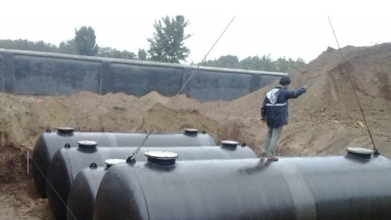
Above ground bulk tanks at a terminal follow a different rulebook, built around legal metrology rather than release detection. That side is set out in our guide to tank gauging.
FAQ
How to check water level in an underground tank?
For a one-off check, lower a clean dip stick or weighted tape through the fill opening and read the wetted length. For a continuous reading, a vented submersible hydrostatic sensor on the tank floor feeds a panel display or telemetry unit. It also adds pump control and low-level alarms.
How much water is in a 100 ft well?
That depends on the casing diameter and how much of it holds water. A 6 inch casing stores about 1.47 gallons per foot, so 100 ft of water column is roughly 147 gallons. A well is measured with a deep well level sensor or a dip tape, not with tank instruments.
How to measure underground water level?
Groundwater level is measured inside a monitoring well or borehole, usually with a submersible pressure sensor hung at a known depth or a manual dip meter. It is a different measurement from a buried tank, where the sensor reads the liquid stored inside a sealed vessel.
How to measure the level of water in a tank?
Either from the bottom or from the top. Pressure-based sensors read the head of water above them and convert it with P = rho x g x h. Radar and ultrasonic units measure the distance down to the surface and subtract it from the tank height.
Request a quote
Tell us the tank depth, the liquid, the opening size available and how far the reading has to travel. We will size the probe or sensor, the cable and the display side, and send datasheets with the proposal. Reach our application engineers or use the form below.
Written and technically reviewed by Wu Peng and the Instranova engineering team.