By Wu Peng, Senior Process Instrumentation Engineer · Last reviewed August 14, 2026
In piping, upstream and downstream describe position along the flow path, not a kind of flow. Upstream is the side the fluid comes from; downstream is the side it goes to. For any reference device (a flow meter, a valve, a pump) the upstream side is its inlet and the downstream side is its outlet.
Those two words carry real engineering weight. Straight-run rules such as 10D upstream and 5D downstream, pressure labels such as P1 and P2, and placement rules for strainers and control valves all assume you know which side is which. This guide defines the terms, gives five field checks for flow direction, and walks through the pressure conventions and placement rules that hang off them.
Contents
- What the terms mean
- Finding the flow direction
- Upstream and downstream pressure
- Instrument placement rules
- Counting straight run
- Upstream in other industries
- FAQ
What the terms mean
The words borrow from rivers. A river flows from its source downhill to its mouth; anything nearer the source is upstream, anything nearer the mouth is downstream. A pipe works the same way. Pick a reference point, and everything the fluid passes before that point is upstream of it, everything it passes after is downstream of it.
The reference point is the part people skip. Upstream and downstream mean nothing on their own; a location is upstream of something. The same block valve can be downstream of the pump and upstream of the flow meter at the same time.
On a P&ID review, say the full phrase: “the strainer upstream of the meter”, “the control valve downstream of the meter”. That habit prevents most arguments.
One reading you will meet in search results is wrong and worth clearing up: upstream flow described as fluid physically moving backward against the main current. In process piping, upstream is a position, not a direction of travel. The fluid at the upstream tap is moving toward the device like everywhere else in the line. Fluid actually running the wrong way has its own name, reverse flow or backflow, and a check valve exists to stop it.
Finding the flow direction
Everything else in this guide depends on knowing which way the fluid moves. On a live line that is rarely written on a sign, so here are the checks I use in the field, roughly in order of reliability.
| Field check | What it tells you |
|---|---|
| Flow arrow on the body | Flow meters, check valves, and many control valves carry a cast or stamped arrow. The arrow points downstream. If the arrow opposes the actual flow, the device is installed backward. |
| Pump flanges | The suction flange is upstream of the pump, the discharge flange is downstream. Trace the pipe away from the discharge and you are walking downstream. |
| Check valve orientation | A check valve only passes flow one way, so its arrow fixes the direction of the whole branch it sits in. |
| Two pressure gauges | On a run with no pump, control valve, or elevation change between them, whichever gauge reads lower is downstream, because friction drops pressure in the direction of flow. |
| The P&ID | Process lines carry direction arrows, and drawings usually read left to right from supply to consumer. On a new line with no fluid in it yet, the P&ID is the only authority there is. |
When two checks disagree, believe the check valve and the pump before the gauges: gauge readings move with elevation and equipment between the taps.
Upstream and downstream pressure
Pressure falls in the direction of flow. Friction removes a little pressure along the run, so for two points on the same run with nothing between them, the upstream point reads higher than the downstream point. The flow rate and pressure relationship guide covers how much it falls and why.
Datasheets compress this into two symbols. P1 is the upstream pressure and P2 is the downstream pressure across a valve, regulator, or flow element. An orifice plate is the textbook example: the high-pressure tap sits upstream of the plate, the low-pressure tap downstream, and the flow reading comes from the difference. The differential pressure flow calculation guide turns that P1 minus P2 into a flow rate.
On a regulator order form the two words decide which product you get, because the two regulator families are told apart by which side they control.
| Device | Which pressure it controls |
|---|---|
| Pressure-reducing regulator | Senses and holds the downstream pressure (P2). It sits at the start of the low-pressure section and protects what comes after it. |
| Back-pressure regulator | Senses and holds the upstream pressure (P1). It sits at the end of a line and keeps everything before it at pressure. |
| Differential pressure element | Uses both. Flow is computed from P1 minus P2 across an orifice plate or similar restriction. |
The phrase “back pressure” itself is the downstream pressure pushing back against the source.
Instrument placement rules
Most placement conventions are one sentence long once the two words are settled. These are the ones that come up on nearly every skid review.
| Component | Where it goes | Why |
|---|---|---|
| Strainer | Upstream of the pump or meter | Debris must be caught before it reaches the rotor or bearings. The strainer is a disturbance itself, so the straight-run count restarts after it. |
| Control valve | Downstream of the flow meter | The valve throws a jet and, when throttling liquids, can flash. Put it downstream and that turbulence is carried away from the sensor rather than into it, and the meter also stays at the higher pressure where gas stays dissolved. |
| Temperature well for compensation | A few diameters downstream of the meter | A thermowell sheds its own wake. Upstream of the meter it would disturb the very profile the meter needs; downstream it disturbs nothing that matters. |
| Flow conditioner | Upstream, between the last fitting and the meter | It breaks up swirl from the fitting so the profile recovers in less length than bare pipe would need. |
| Check valve | Downstream of the pump discharge | When the pump stops, the check valve keeps the downstream column from spinning the pump backward and draining the line. |
| Eccentric reducer | Upstream of the pump suction, usually flat side up | A concentric reducer on a horizontal suction traps an air pocket at the top of the pipe, a known cavitation trigger. The flat top lets gas move on through; when the supply comes from above the pump, the flat side goes down instead. |
Impulse lines for pressure transmitters follow the same logic in miniature: which tap you connect, and how the tubing runs from it, decides what the transmitter sees. The pressure transmitter installation guide covers those rules tap by tap.
Application example
Oil and gas metering skid, Southeast Asia. An operator asked us to replace the turbine meter on an existing liquid metering skid: at about 7 m³/h, the actual flow sat too low in a DN100 meter’s range to read well. We proposed a DN50 turbine meter rated 4 to 40 m³/h, Class 1500, installed between reducers, and the reducer arrangement was acceptable to the client. Each reducer is a new fitting, so the smaller meter’s straight run is counted from the reducer faces.
Counting straight run
Straight-run rules are written in pipe diameters because the physics scales with pipe size. “10D upstream, 5D downstream” means ten internal diameters of straight pipe before the device and five after. On a 4 inch Schedule 40 line (internal diameter 4.026 in), that is about 40 inches before and 20 inches after. Count from the last disturbance, the elbow weld, valve seat, or reducer face, not from the meter flange.
The reason is the velocity profile. An elbow leaves the flow swirling and skewed, and the profile needs distance to relax back to its settled, fully developed shape. Textbook entrance-length estimates put that distance at 4.4 Re1/6 diameters for turbulent flow: about 30D at a Reynolds number of 100,000 and about 44D at 1,000,000. In laminar flow it stretches to 0.06 Re, which is 120D at Re 2,000.
Recovery lengths in the tens of diameters are why profile-sensitive meters ask for numbers that large, and why the generic 10D/5D rule is a workable compromise rather than physics. The Reynolds number guide shows how to place your own line on that scale.
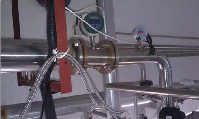
How much straight run a meter actually needs varies enormously. A magnetic flow meter averages the profile and gets by on 5D upstream and 3D downstream. A vortex flow meter is at the demanding end, anywhere from 15D to 40D upstream depending on the design and the fittings ahead of it.
A Coriolis meter does not read the profile at all and needs essentially none. The full by-technology table, the fitting-by-fitting orifice numbers, and the flow conditioner options are in the flow meter straight run requirements guide.
Upstream in other industries
If you searched the bare phrase, half the results are not about pipe at all. The same river metaphor runs through several industries, and it helps to know which sense a document is using.
In the oil and gas business, upstream means exploration and production, midstream means transport and storage, and downstream means refining and distribution. Those are sectors of the industry, not sides of a fitting; a pipe inside a refinery, which the sector definition calls downstream, still has its own local upstream and downstream around every meter and valve.
In supply chains, upstream points at suppliers and downstream at customers. In networking, upstream is the data you send and downstream is the data you receive. This guide, and instrument datasheets generally, use only the piping sense.
FAQ
What is downstream and upstream piping?
Upstream piping is the pipe run before a reference device, carrying fluid toward it; downstream piping is the run after the device, carrying fluid away. For a flow meter, the upstream pipe feeds the inlet and largely decides measurement quality, which is why straight-run rules quote upstream length first.
Which way is upstream vs downstream?
Fluid always moves from upstream to downstream. To orient yourself, find a flow arrow on a meter or check valve (it points downstream), or find a pump: its suction side is upstream, its discharge side is downstream. Pressure also falls from upstream to downstream on an uninterrupted run.
What is an example of upstream and downstream?
Take an orifice plate flow meter. The high-pressure tap P1 sits upstream of the plate, the low-pressure tap P2 downstream, and flow is computed from the difference. On the same line, the strainer belongs upstream of the meter and the control valve downstream of it.
What’s the difference between upstream and downstream?
In piping they are positions along the flow path: upstream is toward the source of flow, downstream is toward the destination. In the oil and gas industry the same words name business sectors, exploration and production versus refining and distribution. Context tells you which sense is meant.
Request a quote
Send us your line size, fluid, flow range, and a sketch or photo of the piping around the planned meter location. Our application engineers will confirm which side is which, check the straight run you actually have, and recommend a meter technology that fits it. Reach our application engineers or use the form below.
Written and technically reviewed by Wu Peng and the Instranova engineering team.