By Wu Peng, Senior Process Instrumentation Engineer · Last reviewed August 5, 2026
Below about 600 °C, an RTD is the accuracy choice: a Class A Pt100 holds ±0.35 °C at 100 °C, where a Class 2 Type K thermocouple is allowed ±2.5 °C. Above 600 °C, the choice makes itself, because platinum RTDs run out of rated range and thermocouples keep going to 1,100 °C and beyond. That is the whole RTD vs thermocouple decision in two sentences; the rest of this guide puts numbers on it.
The numbers matter because the two sensors fail differently. An RTD drifts less than 0.1 °C a year; a Type K element held at 1,200 °C can drift 20 °C in a thousand hours. This guide compares accuracy classes, range limits, response times, drift, wiring cost and vibration tolerance. It closes with a selection table you can hold against your spec sheet.
Contents
- The short answer
- Working principles
- Accuracy compared
- Temperature range compared
- Response time
- Drift and stability
- Wiring and cabling
- Cost of ownership
- Choosing by application
- Where thermistors fit
- Sensors and transmitters
- FAQ
For the full three-way numbers, from beta curves and interchangeability to input-card support, see our thermistor vs thermocouple vs RTD guide.
The short answer
Here is the comparison most spec sheets need, with the numbers the sales tables usually leave out. Each row is expanded in its own section below.
| Property | RTD (Pt100) | Thermocouple (Type K) |
|---|---|---|
| Measures | Resistance of a platinum element | Voltage from two dissimilar metals |
| Tolerance at 100 °C | ±0.35 °C (Class A), ±0.80 °C (Class B) | ±1.5 °C (Class 1), ±2.5 °C (Class 2) |
| Practical range | −200 to about 600 °C | To ~1,100 °C continuous (K); 1,700 °C+ with noble metal types |
| Signal size | ~385 µV per °C at 1 mA | ~41 µV per °C |
| Response (6 mm sheath) | ~13 s in water | ~1.5 s grounded, ~3 s ungrounded |
| Drift | Under 0.1 °C per year in rating | Several °C possible at high temperature |
| Cold junction | Not needed | Required; adds ±0.25 to ±1 °C |
| Vibration | Wire-wound elements vulnerable; thin-film far better | Welded junction tolerates vibration well |
| Element cost | Roughly 2 to 3 times a base-metal thermocouple | Lowest; extension cable can reverse the total on long runs |
Tolerances per IEC 60751 and IEC 60584-1 at 100 °C. Response times are plunge-test values in water; installed assemblies in thermowells respond slower.
Working principles
An RTD is a resistor that happens to be very predictable. A Pt100 element measures 100.00 Ω at 0 °C and rises about 0.385 Ω for every degree. The curve follows the Callendar–Van Dusen equation defined in IEC 60751.
The transmitter pushes a small measuring current through the element, typically 1 mA, and reads the voltage drop. Temperature is computed from resistance.
A thermocouple generates its own signal. Two dissimilar metal wires are welded together at the hot end. The temperature difference between that junction and the instrument terminals produces a small voltage: about 41 µV per °C for Type K.
No excitation current is needed, but the instrument must measure its own terminal temperature to complete the calculation. That cold-junction step is part of every thermocouple measurement, and it carries its own error.
Put the two signals side by side and the accuracy gap starts to explain itself. At 1 mA, a Pt100 delivers about 385 µV per degree; Type K delivers 41 µV per degree.
385 / 41 = 9.4 times more signal per degree for the Pt100
A note on units, because published tables get this wrong: the platinum temperature coefficient is 0.00385 Ω per Ω per °C, which for a 100 Ω element works out to 0.385 Ω/°C. Figures a hundred times larger sometimes appear in comparison tables. If a Pt100 really changed 40 Ω per degree, it would double its resistance by 2.5 °C.
Accuracy compared
Both sensor families have written tolerance classes, so there is no need to argue from adjectives. For platinum RTDs, IEC 60751 defines Class AA at ±(0.1 + 0.0017·t) °C, Class A at ±(0.15 + 0.002·t) °C and Class B at ±(0.3 + 0.005·t) °C.
For thermocouples, IEC 60584-1 gives Type K Class 1 as ±1.5 °C or ±0.4% of reading, whichever is greater. Class 2 allows ±2.5 °C or ±0.75%.
The percentage term takes over above 375 °C for Class 1 and above 333 °C for Class 2. The ASTM E230 equivalents are ±1.1 °C or 0.4% for special limits and ±2.2 °C or 0.75% for standard limits.
Run those formulas at real temperatures and the pattern is clear:
| Sensor temperature | Pt100 Class A | Pt100 Class B | Type K Class 1 | Type K Class 2 |
|---|---|---|---|---|
| 100 °C | ±0.35 °C | ±0.80 °C | ±1.5 °C | ±2.5 °C |
| 300 °C | ±0.75 °C | ±1.8 °C | ±1.5 °C | ±2.5 °C |
| 450 °C | ±1.05 °C (limit) | ±2.55 °C | ±1.8 °C | ±3.4 °C |
| 600 °C | outside class range | ±3.3 °C (limit) | ±2.4 °C | ±4.5 °C |
| 1,000 °C | not available | not available | ±4.0 °C | ±7.5 °C |
IEC 60751 Class A is valid to 450 °C and Class B to 600 °C for wire-wound elements; thin-film validity ranges are narrower. Tolerances apply to new sensors, not aged ones.
The conclusion worth remembering: an RTD is more accurate at every temperature both sensors can reach. The thermocouple never wins on accuracy; it wins on territory. So the real question is not which sensor is better, it is whether your process temperature lets you use an RTD at all.
Temperature range compared
Published range figures for these sensors disagree wildly because three different limits get quoted as if they were one. For Type K, the reference table extends to 1,372 °C, while the tolerance classes stop at 1,000 °C (Class 1) and 1,200 °C (Class 2). The widely recommended continuous service limit for protected, heavy-gauge wire is about 1,100 °C. Between 816 and 1,038 °C in low-oxygen atmospheres, Type K also suffers green rot, a selective oxidation that pulls readings low.
Noble metal types R and S run to about 1,450 °C and Type B to 1,700 °C. Tungsten-rhenium Type C reaches 2,300 °C, but only in non-oxidizing or vacuum service. Our thermocouple types guide covers each type with its tolerance table.
RTDs have the same three-limit structure. Platinum elements can survive from −200 °C to 850 °C in special constructions. The accuracy classes, though, are only valid to 450 °C (Class A) or 600 °C (Class B) for wire-wound elements. Thin-film elements are commonly rated to 500 or 600 °C.
In practice, industrial RTD assemblies are specified below about 600 °C, and above that the choice defaults to a thermocouple. When a comparison table tells you RTDs stop at 400 °C, it is usually describing one vendor’s product line, not the technology.
Response time
Thermocouples are faster, but only when construction is equal. In plunge tests in water, an exposed fine-wire junction responds in hundredths of a second. A 3 mm mineral-insulated thermocouple with an ungrounded junction takes about 0.8 s, and a grounded junction roughly halves that.
A 6 mm sheathed Pt100 needs on the order of 13 s on the same plunge-test basis. That is about an order of magnitude behind a grounded thermocouple of the same diameter.
Two caveats keep this from being a simple rule. First, an ungrounded thermocouple in a large sheath can respond more slowly than a compact thin-film RTD. The sheath and insulation set the lag, not the sensing physics.
Second, once either sensor goes inside a thermowell, the well dominates the time constant and the difference between the two sensors mostly disappears. If loop speed matters, specify the smallest sheath and tip design the process allows before switching sensor families.
Drift and stability
This is the least visible difference and the most expensive one. A quality industrial RTD used within its rating drifts less than 0.1 °C per year, with good sensors specified below 0.05 °C per year. A thermocouple’s alloys change composition with time at temperature. Published tests on conventional mineral-insulated Type K probes show drift approaching 20 °C after 1,000 hours at 1,200 °C.
Type K also picks up a reversible few-degree error, the K-state, when cycled between 250 and 600 °C. There is no defensible single drift-per-year figure for a thermocouple; drift depends on temperature, atmosphere, sheath and wire gauge.
The practical rule: where readings feed quality records or custody decisions, use the RTD. It keeps its calibration between checks in a way no base-metal thermocouple will at high temperature. Thermocouples in hot service need shorter verification intervals. The difference between checking and adjusting is worth understanding; our guide to calibration vs verification covers it.
Wiring and cabling
RTD errors live in the copper. The element only changes 0.385 Ω per degree, so every ohm of lead wire reads as 2.6 °C if nothing compensates for it. A 10 m two-wire run in 22 AWG adds about 1.05 Ω of loop resistance, which reads as 2.7 °C. That is more than three times the entire Class B budget at 100 °C.
Three-wire circuits cancel most of that and leave only the mismatch between leads, typically 0.1 Ω or 0.26 °C; four-wire circuits remove lead resistance entirely. The full treatment, including a wire-gauge error table, is in our 3-wire RTD wiring guide.
Thermocouple errors live in the cable type and the cold junction. Every meter between sensor and instrument must be thermocouple extension or compensating cable of the matching type. Splice in plain copper and the reading shifts by the temperature difference across the splice. The instrument’s cold-junction compensation then adds its own ±0.25 to ±1 °C depending on the transmitter or input card.
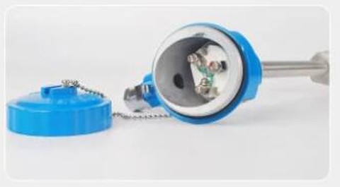
Thermocouple pairs also pick up induced AC noise when routed parallel to power cables, a real effect at 41 µV per degree. Keep those runs perpendicular to power, or shielded. The clean way out for both families is a head-mounted temperature transmitter. Convert to 4-20 mA at the sensor, then run ordinary instrument cable the rest of the way.
Cost of ownership
On element price, the thermocouple wins: an RTD of similar construction commonly costs two to three times as much. On installed cost, the picture can invert. Thermocouple extension cable costs several times plain instrument cable per meter, and it must run the whole distance; an RTD runs on ordinary copper.
On a long run, the cable difference can exceed the sensor difference. That is why the head transmitter plus copper approach became the default in large plants.
Add lifetime effects and the accounting shifts further. A thermocouple in hot service is a consumable that drifts toward replacement; an RTD below 600 °C typically outlasts several calibration cycles unchanged. Price the sensor, the cable and the recalibration interval together before calling either one cheaper.
Choosing by application
Start with temperature, then let accuracy, vibration and speed break the ties.
| Situation | Pick | Why |
|---|---|---|
| Process below 300 °C, tolerance tighter than ±1 °C | RTD, Class A | No standard-limit thermocouple meets a ±1 °C spec |
| Furnace, kiln or exhaust, 600 to 1,100 °C | Thermocouple, K or N | Beyond RTD class validity; N resists drift better than K |
| Above 1,300 °C | Thermocouple, R, S, B or C | Only noble metal and tungsten-rhenium types survive |
| Heavy vibration: pumps, gearboxes, bearing blocks | Thin-film RTD or thermocouple | Wire-wound RTD coils fatigue; welded junctions and bonded films hold up |
| Fast control loop on a small line | Grounded thermocouple | Sub-second response in small sheaths |
| Cryogenic service to −200 °C | RTD (or Type T) | Pt100 is rated to −200 °C; Type T is the thermocouple fallback |
| Quality records, audits, batch documentation | RTD | Sub-0.1 °C annual drift keeps records defensible |
Application example
Mining, process water and slurry. A mining operation asked for ten PT100 resistance sensors for process water and slurry lines, spanning 0 to 200 °C, with line pressures around 10 bar to be confirmed at the proposal stage. That range sits comfortably inside the RTD class limits: at 200 °C a Class A element holds ±0.55 °C, a tolerance no standard-limit thermocouple matches. We proposed PT100 assemblies covering 0 to 200 °C for all ten measurement points.
Where thermistors fit
The three-way comparison keeps coming up, so here is the short version. A thermistor is a semiconductor resistor that changes tens of ohms per degree, against a fraction of an ohm for a Pt100. That makes it extremely sensitive over a narrow window, typically −50 to 150 °C, and strongly nonlinear outside a small span. That profile suits OEM equipment, HVAC and appliance control.
In process plants, thermistors are rare for a practical reason. Almost no industrial transmitters, PLC input cards or DCS channels accept them, while every temperature input on the market takes a Pt100 or a Type K. For plant instrumentation, the real decision stays RTD vs thermocouple.
Sensors and transmitters
Both families are stock configurations for us. The WZP series Pt100 RTD covers −200 to 650 °C with Class A or Class B elements and 2, 3 or 4-wire terminals. The WRN and WRP series thermocouples cover Type K through the noble metal types.
Either one pairs with a head-mounted or field-mounted transmitter with universal input. A later change of sensor family then costs a configuration setting, not a rewire. The full range is on our temperature sensor lineup page.
Both element families end up wired into the same recorders, and the cold junction penalty on a thermocouple input shows up directly in the recorded value. That side is worked through under paperless chart recorders.
For a deeper look at the millivolt side of this comparison, our guide to how a thermocouple works walks through the Seebeck effect and cold junction compensation.
FAQ
How to tell an RTD from a thermocouple?
Measure resistance at the sensor terminals. A Pt100 RTD reads about 108 Ω at room temperature and usually has three or four leads. A thermocouple reads close to zero ohms and has exactly two conductors of dissimilar metals. On Type K the negative leg is weakly magnetic, which a shop magnet will confirm.
Is a Pt100 a thermocouple or RTD?
A Pt100 is an RTD. The name means a platinum element with a resistance of 100 Ω at 0 °C, standardized in IEC 60751. Its temperature coefficient is 0.00385 Ω/Ω/°C. Pt500 and Pt1000 are the same technology with higher base resistance, which reduces the effect of lead-wire errors.
Our digital temperature gauge, for example, reads a Class A Pt1000 element on a 4-digit LCD.
What is the difference between thermocouple and RTD table?
The table at the top of this guide compares the two line by line. Compressed to three points: an RTD measures the resistance of a platinum element and is the accuracy and stability choice below about 600 °C. A thermocouple generates a millivolt signal and covers everything hotter. Both usually feed the same 4-20 mA temperature transmitter.
Why is RTD more accurate than thermocouples?
An RTD measures a bulk, stable property: the resistance of pure platinum, which delivers about nine times more signal per degree than a Type K couple. A thermocouple output is microvolts riding on wire alloy uniformity. On top of that, the cold-junction measurement adds ±0.25 to ±1 °C before the sensor tolerance even starts.
Request a quote
Tell us the application: temperature range, required tolerance, insertion length and process connection. Mention whether the point feeds a control loop or a quality record. We will configure the sensor and transmitter to match, not hand you a shelf part. Reach our application engineers or use the form below.
Written and technically reviewed by Wu Peng and the Instranova engineering team.