By Wu Peng, Senior Process Instrumentation Engineer · Last reviewed September 22, 2026
A thermistor is a metal-oxide semiconductor resistor that trades range for sensitivity. Near room temperature its resistance moves about 4 percent per degree, more than ten times the signal of a Pt100. The accurate window, though, is only about −50 to 150 °C.
A platinum RTD is the standardized, stable choice up to roughly 600 °C in industrial assemblies. A thermocouple reaches furthest, with Type K reference tables running to 1,372 °C.
This guide puts numbers on the thermistor vs thermocouple vs RTD decision that most published comparisons leave out. That means interchangeability tolerances, self-heating, lead-wire arithmetic and which instrument inputs accept each sensor.
One boundary first: a thermostat is a switch that opens or closes at a set point, not a measuring sensor. Appliance repair questions about dryers, water heaters or 3D printers sit outside this page. For the two-way plant decision in depth, see our RTD vs thermocouple guide.
Contents
- Three sensors compared
- How each works
- NTC and PTC
- Sensitivity and signal
- Range and drift
- Accuracy and interchangeability
- Beta and linearization
- Self-heating
- Lead wires
- Instrument inputs
- Choosing by application
- Application note
- FAQ
Three sensors compared
The RTD vs thermistor choice is mostly about standardization against sensitivity. The thermocouple enters whenever temperature or speed rules the other two out. The table shows the numbers the rest of this page works through.
| Property | Thermistor (NTC) | RTD (Pt100) | Thermocouple |
|---|---|---|---|
| Element | Sintered metal-oxide semiconductor | Platinum wire or film, 100 Ω at 0 °C | Welded junction of two alloys |
| Signal near 25 °C | About −440 Ω per °C on a 10 kΩ part | 0.385 Ω per °C | About 41 µV per °C (Type K) |
| Usable range | −50 to 150 °C epoxy; glass builds to about 300 °C | −200 °C to about 600 °C in industrial assemblies | −200 °C to 1,372 °C table (Type K); about 1,100 °C continuous |
| Interchangeability | No international standard; curve-matched parts to ±0.1 or ±0.2 °C, 0 to 70 °C | IEC 60751 Class AA, A, B | IEC 60584-1 Class 1, 2 |
| Where it wins | Building controls, OEM equipment, narrow spans on a budget | Process plants that need accuracy and a swappable sensor | High temperature, fast response, rugged points |
Range and tolerance figures follow IEC 60751, IEC 60584-1 and manufacturer package ratings; the sections below give the sources and the arithmetic.
How each works
An NTC thermistor is a bead or disc of sintered metal oxides. Heat frees more charge carriers in the semiconductor, so resistance falls steeply as temperature rises. That is where both the huge sensitivity and the strong nonlinearity come from. A platinum RTD works the opposite way and far more gently: resistance rises with temperature along a nearly straight, internationally tabulated curve.
A thermocouple generates its own millivolt signal along the temperature gradient between the measuring junction and the reference junction, so it needs no excitation current at all. Our guide on how a thermocouple works walks through that chain, and the RTD vs thermocouple comparison covers the two plant sensors point by point.
NTC and PTC
Measurement thermistors are NTC parts: negative temperature coefficient, resistance falls as temperature rises. PTC thermistors do the reverse and serve mainly as protectors rather than sensors. Motor-winding PTC probes sit near a switching threshold and jump to high resistance when the winding overheats, tripping a relay or a drive input. Inrush-limiting PTC and NTC discs manage current, not measurement.
So when a motor protection relay advertises a thermistor input, it means a PTC trip circuit with a threshold, not a temperature reading. Everything else on this page is about NTC measurement parts.
Sensitivity and signal
Manufacturers quote NTC temperature coefficients between about −3.3 and −4.9 percent per degree at 25 °C. On a 10 kΩ part with a 3950 K beta that works out to roughly 440 Ω per degree. A Pt100 moves 0.385 Ω per degree, or 0.385 percent of its nominal resistance. A Type K thermocouple delivers about 41 µV per degree.
In relative terms the thermistor carries more than ten times the signal of platinum. On lower-resistance parts the same coefficient shows up as tens of ohms per degree.
That sensitivity is not flat. The same 10 kΩ curve is down to about 700 Ω at 100 °C, moving about 20 Ω per degree there, still 2.8 percent per degree of what remains. The big raw signal is what lets simple two-wire circuits work, as the lead-wire section shows.
Range and drift
Packaging, not the oxide, sets the thermistor ceiling. Epoxy-coated parts are typically rated between 105 and 150 °C depending on the vendor.
TE Connectivity rates its epoxy line to 125 °C and its glass and hermetic DO-35 parts to 300 °C. Ametherm puts the best-accuracy window at −50 to 150 °C, with glass builds to about 250 °C. Above those limits the choice is no longer a thermistor question.
Platinum elements survive −200 to 850 °C in special constructions, but industrial RTD assemblies are, in practice, ordered for service below roughly 600 °C. Above that the default is a thermocouple. Type K tables run to 1,372 °C with about 1,100 °C as the continuous service limit for heavy protected wire. The thermocouple types guide maps each letter type.
Drift is a packaging decision too. Ametherm quotes epoxy-coated NTC drift at 0.2 °C per year against 0.02 °C per year for hermetically sealed glass, a factor of ten for the same oxide. RTD and thermocouple drift behavior, including where each mechanism comes from, is covered in the two-way guide.
Accuracy and interchangeability
Platinum tolerances come straight from IEC 60751: Class AA is ±(0.1 + 0.0017·t) °C, Class A is ±(0.15 + 0.002·t) °C, with Class B at ±(0.3 + 0.005·t) °C. At 25 °C that puts a Class A element inside ±0.20 °C.
Thermocouples carry IEC 60584-1 Class 1 and 2 limits per letter type. Any vendor on either curve is held to the same numbers, which is what makes replacement sensors a stock item.
Thermistors have no equivalent international interchangeability standard. What vendors sell instead is curve matching: TE Connectivity offers interchangeable parts at ±0.2 °C from 0 to 70 °C with ±0.1 °C grades available. Vishay documents curve tracking at ±0.2, ±0.5 and ±1.0 °C over the same span. Inside that window a ±0.1 °C matched thermistor beats Class A platinum; outside the window no tolerance is defined at all.
The trap is that a resistance value is not a curve. Two of the common 10 kΩ curve types both read 10 kΩ at 25 °C yet publish 32,650 Ω (Type 2) against 29,490 Ω (Type 3) at 0 °C. The gap is 3,160 Ω, or 9.7 percent.
On the roughly 1,700 Ω per degree slope at that point, swapping one for the other shifts the reading by about 2 °C. Published substitution examples run higher still further down the curve. Order replacements by curve designation, never by nominal resistance alone.
Beta and linearization
Thermistor curves are usually summarized by a beta constant fitted between two temperatures, commonly 25 and 85 °C or 25 and 50 °C:
R(T) = R25 · exp[ β (1/T − 1/298.15) ] (T in kelvin)
A 10 kΩ, 3950 K part falls to about 1.06 kΩ at 85 °C by its published lookup table: a 9.4:1 resistance swing in 60 degrees. A Pt100 covers 100 to 138.5 Ω across the full 0 to 100 °C span, a 1.39:1 swing. The thermistor gives an analog input an enormous signal, and in exchange the instrument must carry the linearization.
The beta equation holds well over narrow spans. For wider ones, the three-coefficient Steinhart-Hart fit keeps the error under about 0.02 °C across a 200-degree span. The coefficients belong to one curve and come from the vendor table, not from a universal list.
Platinum needs far less help: its standard equation is close to a straight line with a slight bow. Every process transmitter carries it, along with the thermocouple polynomials. It is one reason plant instruments list RTD and thermocouple inputs first, as the input section shows.
Self-heating
Any resistive sensor is warmed by its own excitation. Thermistor datasheets specify it as a dissipation constant in mW per degree, set by the package and the medium. One vendor rates a 5 mm epoxy disc at about 4.5 mW per °C. A small bead lists 1 mW per °C in still air and 13 mW per °C in stirred oil, a thirteen-fold spread for the same part.
In the classic 5 V divider with a 10 kΩ fixed resistor, the thermistor drops 2.5 V at 25 °C, so it dissipates 2.5²/10,000 = 0.625 mW. The result is a 0.14 °C high reading on the 4.5 mW per °C disc, and about 0.6 °C high for the 1 mW per °C bead in still air.
A Pt100 at the standard 1 mA measuring current dissipates 0.1 mW. At datasheet self-heating coefficients of 0.4 to 0.5 °C per mW, that is a 0.04 to 0.05 °C rise. A thermocouple generates its own voltage and draws no excitation, so self-heating does not exist for it. The self-heated reading always sits high, because the element really is warmer than the process around it.
Lead wires
Copper cable resistance lands very differently on the three sensors. Ten meters of 22 AWG cable is about 1.06 Ω out and back. On a two-wire Pt100 that ohm reads 2.75 °C high.
On a 10 kΩ thermistor the same ohm is buried in ten thousand, about 0.002 °C. It nudges the reading low, because extra resistance looks colder on a falling curve.
The gap is roughly a thousand times. It is why building controllers run thermistors two-wire over long cable.
Platinum installations solve the same ohm with geometry instead: the 3-wire RTD guide covers how 3-wire and 4-wire connections cancel lead resistance. Thermocouples have a different cable problem entirely, matched extension and compensating wire, because their signal lives in the alloys, not in the resistance.
Instrument inputs
In a process plant the sensor decision is constrained by what the input electronics accept. Here the thermistor mostly loses by omission.
The Rosemount 644 lists RTD, thermocouple, millivolt and ohm inputs, and the Yokogawa YTA series lists the same four. Our own SI-SBW temperature transmitter takes Pt100, Cu50 and Cu100 RTDs plus seven thermocouple types. None of these lists an NTC thermistor curve.
| Input electronics | Accepted sensors | Thermistor |
|---|---|---|
| Universal process transmitters | RTD, thermocouple, mV, ohm | Not listed |
| PLC and DCS temperature cards | RTD curves and thermocouple types | Rare |
| Building automation controllers | 10 kΩ thermistor curves native | First-class input |
| Dedicated thermistor transmitters | One thermistor curve to 4-20 mA | By design |
Input lists per the Rosemount 644 and Yokogawa YTA data sheets; HVAC vendors such as BAPI sell thermistor-input transmitters for the building world. National Instruments documents thermistor wiring on its universal DAQ module as a workaround rather than a designed configuration.
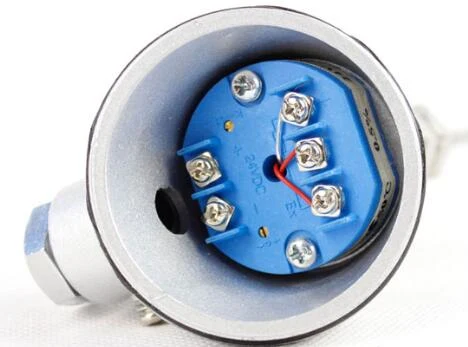
If a design must keep a thermistor and still speak 4-20 mA, the path is a dedicated thermistor transmitter or a controller that carries the curve. In practice the simpler route is the reverse: specify the sensor the instrumentation already understands.
Choosing by application
A thermistor vs thermocouple vs RTD comparison only settles anything once the application is on the table, so here is the short routing.
| Application | Pick | Why |
|---|---|---|
| Building automation, HVAC, OEM equipment | NTC thermistor | Native controller input, two-wire cabling, lowest cost per point |
| Process measurement to about 600 °C | Pt100 RTD | IEC 60751 classes, stability, any transmitter accepts it |
| Above 600 °C, or fast and rugged points | Thermocouple | Range to 1,372 °C tables, small fast junctions, survives vibration |
| Narrow span needing 0.1 °C class accuracy near ambient | Matched thermistor or Class AA RTD | Curve-matched NTC wins inside 0 to 70 °C if the input exists |
| Motor winding protection | PTC probe or Pt100 | PTC trips a relay; Pt100 gives a continuous reading |
For plant work the product pages carry the specifications: our Pt100 RTD assemblies and thermocouple sensors both pair with the head-mount transmitter above. The two-way accuracy, drift and wiring detail lives in the RTD vs thermocouple guide.
Application note
Application example
What our inquiry log says. Not one of the 330 inquiries in our project records asks for a thermistor. The temperature requests are Pt100 assemblies, thermocouples and head-mount transmitters, since a process RFQ is written around the input card that will read the sensor. Thermistors are bought as components inside OEM equipment and building controllers, through a different supply chain, which matches where this page routes them.
FAQ
What is the difference between an RTD, thermocouple, and thermistor?
All three measure temperature through different physics. An RTD is a platinum resistor with a standardized, nearly linear curve to about 600 C in industrial use. A thermocouple generates millivolts from two joined alloys and reaches the highest temperatures. A thermistor is a semiconductor resistor with the strongest signal over a narrow window, roughly minus 50 to 150 C.
Is a PT100 a thermistor or an RTD?
A Pt100 is an RTD, not a thermistor. It is a platinum resistance element defined by IEC 60751 at 100 ohms at 0 C, rising about 0.385 ohms per degree. A thermistor is a metal-oxide semiconductor, far more sensitive, and follows no international interchangeability standard; the common NTC type falls in resistance as temperature rises.
What is the difference between a thermocouple and a thermostat?
A thermocouple is a sensor: it outputs a small voltage that an instrument converts into a temperature reading. A thermostat is a switch: it opens or closes a contact at a set temperature and reports nothing in between. Many appliances use a thermostat for control even when a separate sensor does the measuring.
What is the purpose of a thermistor?
An NTC thermistor measures temperature by changing resistance around 4 percent per degree, which gives simple electronics a large, cheap signal over a narrow range. It dominates building controls, appliances and OEM equipment. PTC thermistors serve protection instead, tripping motor relays or limiting inrush current rather than reporting a temperature.
Request a quote
Tell us the application: the temperature span, the accuracy you need and what will read the sensor. We will size a Pt100 assembly, a thermocouple or a sensor-plus-transmitter pair around it, not a shelf part. Reach our application engineers or use the form below.
Written and technically reviewed by Wu Peng and the Instranova engineering team.