By Wu Peng, Senior Process Instrumentation Engineer · Last reviewed July 20, 2026
A U-tube manometer is a U-shaped tube, roughly half filled with liquid, that measures pressure by hydrostatic balance. Apply pressure to one leg and the liquid falls on that side and rises on the other. The height difference h between the two columns is the measurement itself: P = rho x g x h, where rho is the liquid density. A 250 mm difference on a water-filled manometer equals 2.45 kPa (0.355 psi). Nothing else in pressure measurement is this direct.
The manometer is the oldest pressure instrument still in service, and for low gas pressures it remains the reference everything else is checked against. It needs no power, no electronics, and no calibration; the reading depends only on the liquid density and local gravity. This guide covers the working principle, the manometer equation, how to read the columns correctly, fluid selection, U-tube, well-type, and inclined designs, three worked calculations, the error sources that actually matter, and the point where a differential pressure transmitter becomes the better choice.
Contents
- How it works
- The manometer equation
- Reading a manometer
- Manometer fluids
- Manometer types
- Worked examples
- Error sources
- Manometer or transmitter
- FAQ
How it works
With both legs open to atmosphere, the liquid sits at the same level on each side. Connect a gas pressure to one leg and the liquid moves until the weight of the displaced column exactly balances the applied pressure. The column stops moving when hydrostatic equilibrium is reached, and the vertical distance between the two liquid surfaces reports the pressure.
How you connect the legs decides what you measure. With one leg open to atmosphere, the manometer reads gauge pressure, positive or vacuum. With both legs piped to two process points, it reads the differential pressure between them; this is the classic way to read the drop across an orifice plate, a filter, or a pitot tube.
Because the reading depends only on density, gravity, and a length, the manometer is a primary standard. Tube bore, tube shape, and even an uneven bore between the two legs do not change the result. That is why calibration benches kept mercury columns long after transmitters took over the plant floor: a clean manometer cannot drift.
The manometer equation
The pressure balance across the two liquid surfaces gives the working formula.
P = rho x g x h
P is the pressure in pascals, rho the fluid density in kg/m³, g the gravitational acceleration (9.807 m/s²), and h the height difference in meters. Two per-millimeter values are worth memorizing: 1 mm of water is 9.8 Pa and 1 mm of mercury is 133.3 Pa. In imperial units, 1 inch of water column (inWC) is 249 Pa, and 27.68 inWC make 1 psi. Manometer scales are the reason pressure is still quoted in inWC, mmH2O, and mmHg; our pressure units guide covers the family, and the pressure unit converter moves any reading between them.
One assumption hides in the simple formula: the fluid above the manometer liquid is a gas light enough to ignore. If the process fluid is a liquid that fills the connecting leg, its own column pushes back, and the equation becomes P = (rho m − rho p) x g x h, where rho m is the manometer fluid density and rho p the process liquid density. With water standing over mercury, for example, skipping the correction overstates the pressure by about 8 percent. With one leg open, the result is gauge pressure; the absolute and gauge pressure calculator converts it to absolute when a datasheet asks for it.
Reading a manometer
Three habits separate a good reading from a guess. First, take the difference of both legs, not one. When pressure is applied, the fluid drops on one side and rises on the other; h is the total distance between the two surfaces. Scales on U-tube instruments are usually zeroed at the rest level, so you add the reading above zero to the reading below zero. If you only glance at one leg you halve the measurement.
Second, read at eye level. Looking down or up at the column shifts the apparent level against the scale; a 10 degree sight angle on a 6 mm bore tube is enough to move the reading a full millimeter.
Third, read the correct part of the meniscus. Water wets glass and curves upward at the edges, so you read the bottom of the curve. Mercury does not wet glass and bulges upward, so you read the top. Whichever fluid is in the tube, be consistent on both legs and the residual error cancels.
Manometer fluids
The fluid sets the span and the resolution. A dense fluid compresses the column so more pressure fits in the same tube length; a light fluid stretches it so small pressures become readable. Density values below are for fluids near room temperature.
| Fluid | Density (kg/m³) | 1 mm of column | Practical span per meter of tube |
|---|---|---|---|
| Red gauge oil (SG 0.826) | 826 | 8.1 Pa | About 8 kPa; finest resolution, standard fill in draft gauges |
| Water | 998 | 9.8 Pa | About 10 kPa; cheap, but evaporates and freezes |
| Mercury | 13,560 | 133.3 Pa | About 133 kPa; high spans, toxic and increasingly restricted |
Colored gauge oil is dyed for visibility and has a low vapor pressure, so the column does not fade by evaporation the way plain water does.
Beyond density, the fluid must not mix with or dissolve into the process gas, and its vapor pressure must be low at the operating temperature. Density also moves with temperature, which is one of the error sources covered below.
Manometer types
Three liquid-column layouts cover almost every application, and they differ mainly in how the scale is arranged.
| Type | How it reads | Where it fits |
|---|---|---|
| U-tube | Both legs read, difference taken | General purpose, calibration reference, teaching |
| Well type | One wide reservoir, one tube; single scale read directly | Panel mounting, barometers, anywhere one-glance reading matters |
| Inclined (draft gauge) | Tube sloped; fluid travels far along the scale for a small rise | Furnace draft, filter DP, room pressure in the inWC range |
The well type trades a little accuracy for convenience: as fluid rises in the tube, the well level drops slightly, so factory scales are compressed by the tube-to-well area ratio to compensate. Read a well-type instrument only with its own scale.
The inclined manometer solves a resolution problem. Lay the tube at a slope where sin(theta) = 0.1 and the fluid must travel 100 mm along the scale to gain 10 mm of vertical height. The vertical rise is what carries pressure, so the slope multiplies scale travel, and therefore resolution, by ten. This is how a draft gauge resolves a few pascals of furnace draft with nothing but oil and glass. The same low ranges show up when reading velocity pressure from a pitot tube; our guide to static, dynamic, and total pressure covers that measurement.
A mercury barometer is a special case: a sealed, evacuated tube standing in a mercury well, reading absolute atmospheric pressure. The barometric pressure guide covers it separately.
Worked examples
Three calculations cover the everyday cases. All use g = 9.807 m/s².
1. Water manometer on a gas duct. The columns settle 250 mm apart.
P = 998 x 9.807 x 0.250 = 2,447 Pa = 2.45 kPa = 9.82 inWC = 0.355 psi
2. Mercury manometer on a compressed gas line. The difference is 300 mm.
P = 13,560 x 9.807 x 0.300 = 39.9 kPa = 5.79 psi
Note the density sensitivity: use the 0 °C mercury value of 13,595 kg/m³ and the same column reads 40.0 kPa. A quarter percent shift from the density assumption alone is the accuracy class of a decent transmitter, which is why serious mercury work always states the fluid temperature.
3. Inclined gauge at a 1:10 slope. The oil travels 100 mm along the scale. Vertical rise = 100 x 0.1 = 10 mm. With water-equivalent fluid that is 98 Pa (0.39 inWC). On a vertical tube, 10 mm is barely readable; on the slope it is a clean 100 mm sweep.
Error sources
A manometer has no electronics to fail, so its errors are all physical and all visible if you know where to look.
- Parallax and meniscus. Reading off eye level, or reading the wrong part of the curve, costs a millimeter or two; on a 25 mm draft reading that is nearly 10 percent.
- Temperature. Fluid density falls as temperature rises, roughly 0.02 percent per °C for water and mercury near room temperature. Precision work corrects the reading to a reference temperature.
- Capillarity. In bores under about 6 mm, surface tension lifts or depresses the column noticeably. Matched bore on both legs cancels most of it, which is one more argument for buying a manufactured instrument rather than bending glass tube.
- Off-level mounting. A vertical U-tube forgives a small tilt; an inclined gauge does not. Level the instrument to its bubble before zeroing, every time it is moved.
- Overrange blowout. Exceed the column and the fluid blows out of the tube into the process line. A water manometer holds barely 10 kPa per meter of tube, so a modest pressure surge empties it. This failure mode, plus the cleanup, is a common reason gas utilities retired liquid columns.
- Mercury itself. Toxic vapor, strict disposal rules, and shrinking regulatory tolerance. Many sites now ban new mercury instruments outright, which forces the replacement question below.
Manometer or transmitter
Keep a manometer where its strengths matter: commissioning spot checks, calibration benches, teaching, and any local indication where zero power and zero drift beat convenience. Replace it where the weaknesses cost money: anywhere the reading must travel to a control system, log a trend, trip an alarm, or survive an overrange without blowing fluid into the line.
The electronic successor is the differential pressure transmitter, which reads the same taps a U-tube did and outputs 4-20 mA. For low gas ranges in the kilopascal band, the territory of water columns, a dedicated low pressure transducer holds accuracy where a general purpose unit runs out of turndown. Where a digital local display plus RS485 is enough, a digital pressure sensor does the job without any liquid. The full line is under pressure instruments.
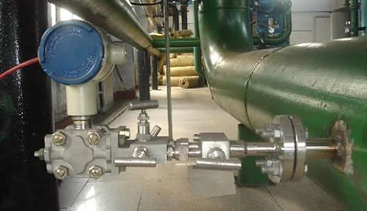
Application example
Pharmaceutical plant, Pakistan. The HVAC team needed room-to-room differential pressure indication across cleanroom suites. Design figures sat in the tens of pascals; cleanroom practice typically holds up to about 60 Pa between adjacent rooms (industry-typical values, not client measurements). At 30 Pa a water column stands 3 mm tall, unreadable at a glance, so we specified dry diaphragm DP gauges, the dial descendants of the inclined manometer, with a low-range DP transmitter option for rooms that report to the building management system. Operators get a pointer they can read from the corridor, with no fluid to top up or re-level.
FAQ
What is a U-tube manometer?
A U-tube manometer is a U-shaped tube partly filled with liquid, used to measure pressure. Pressure applied to one leg displaces the liquid, and the height difference between the two columns, multiplied by fluid density and gravity, equals the applied pressure. It needs no power or calibration.
How does the U-tube manometer work?
It works by hydrostatic balance. The applied pressure pushes the liquid down one leg and up the other until the weight of the displaced column balances the pressure. The reading is the vertical distance h between the two liquid surfaces, converted by P = rho x g x h.
What is the U-tube manometer used for measuring?
Mostly low gas pressures: furnace and chimney draft, duct static pressure, filter differential pressure, gas supply pressure, and pitot velocity pressure. Water columns cover up to about 10 kPa per meter of tube, mercury up to about 133 kPa, and inclined oil gauges resolve single pascals.
How to read pressure in a U-tube manometer?
Read both legs at eye level and take the total difference: the amount one column fell plus the amount the other rose. Read the bottom of a water meniscus and the top of a mercury meniscus, the same way on both legs, then multiply the height by fluid density and g.
Request a quote
If a liquid column is no longer enough, whether the range is a few pascals of room pressure or full line pressure, tell us the application and we configure one unit, not a shelf part. Reach our application engineers or use the form below.
Written and technically reviewed by Wu Peng and the Instranova engineering team.