By Wu Peng, Senior Process Instrumentation Engineer · Last reviewed July 24, 2026
Orifice plate tappings are the pressure connections that let a differential pressure transmitter read the drop across the plate. ISO 5167-2 recognizes three arrangements: corner tappings at the plate faces, flange tappings 25.4 mm (1 in) either side, and D and D/2 tappings one pipe diameter upstream and half a diameter downstream. Which one you pick is baked into the discharge coefficient, so it has to be fixed before the meter can be sized.
This guide gives the exact distances and tolerances for each tapping, explains why the choice changes the coefficient (and why you cannot swap tappings without recalculating), and gives a plain decision on which to use. It covers tap orientation, drain and vent holes, and what to state on the order.
Contents
- Why location matters
- The three arrangements
- Vena contracta and pipe
- Effect on the coefficient
- Choosing a tapping
- Orientation and drain holes
- Specifying on the order
- FAQ
Why location matters
An orifice plate speeds the flow through its bore, so static pressure drops. The lowest pressure is not at the plate but a short distance downstream, at the vena contracta, where the jet is narrowest. Move the downstream tap and you read a different pressure for the same flow. That is the whole reason there is more than one tapping standard, and why the tapping type is written into the orifice plate flow equation rather than left to the installer. Get the tap wrong and the meter reads the wrong flow, even with a perfect plate. The flow itself still follows the square-root law common to every differential pressure flow meter, which our guide on the flow rate and pressure relationship explains.
The three arrangements
ISO 5167-2 covers exactly three tapping types, and any orifice you buy to that standard uses one of them. The distances below are measured from the relevant plate face; the tolerances are what the standard allows before the coefficient has to be re-derived.
| Tapping | Upstream tap | Downstream tap | Where it fits |
|---|---|---|---|
| Corner | At the upstream face | At the downstream face | Small pipe; standard across Europe; needs a special carrier or drilled flange |
| Flange | 25.4 mm (1 in) from the face | 25.4 mm (1 in) from the face | The default from 2 in up; taps drilled in the orifice flanges |
| D and D/2 | 1D from the face | 0.5D from the face | Large bore and high Reynolds; taps in the pipe wall, not the flange |
Flange spacing tolerance is ±0.5 mm for β above 0.6 with D below 150 mm, and ±1 mm otherwise. For D and D/2, the upstream tap may sit anywhere from 0.9D to 1.1D without changing the coefficient. Each tap bore stays below 0.13D and below 13 mm.
Corner tappings sit right at the plate, either as a single drilled hole whose center is about half its own bore from the face, or as an annular slot that averages pressure all the way round. They are the European default on every size and the usual choice below 2 in, because on a small pipe the vena contracta falls so close to the plate that a downstream flange tap would read in the wrong place. Their drawback is cost: corner taps need a special orifice carrier or specially drilled flanges rather than plain ones.
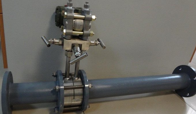
Flange tappings are drilled 25.4 mm each side, straight into a pair of orifice flanges. They are the North American default from 2 in up, because the tap is machined into an off-the-shelf orifice flange to ASME B16.36 (classes 300# through 2500#, with no 150# in the range). Below about 1.5 to 2 in they are not used, since 25.4 mm downstream lands too far past the vena contracta.
D and D/2 tappings, also called radius taps, sit in the pipe wall one diameter upstream and half a diameter downstream, so the downstream tap sits near the vena contracta for a wide range of beta. Because they are drilled in the pipe, not the flange, they suit large lines and welded meter runs where machining orifice flanges would be expensive.
Vena contracta and pipe
Two older arrangements still turn up on drawings, and neither is in ISO 5167-2. Vena contracta taps put the upstream tap at 1D and the downstream tap right at the minimum-pressure point, roughly 0.3D to 0.8D depending on beta and Reynolds number. They give the largest differential, but the exact spot moves as flow changes, so they are hard to standardize. Pipe, or full-flow, taps sit 2.5D upstream and 8D downstream, where the pressure has already recovered; they are the least accurate and are mostly seen on old gas runs. If you inherit either type, treat the coefficient as tap-specific and recalculate rather than assuming an ISO value.
Effect on the coefficient
The tapping is not just a mounting detail. ISO 5167-2 sets the discharge coefficient with the Reader-Harris/Gallagher equation, and that equation carries two terms, L1 and L2′, that are the upstream and downstream tap distances expressed in pipe diameters. Their values are different for each tapping type:
| Tapping | L1 (upstream) | L2′ (downstream) |
|---|---|---|
| Corner | 0 | 0 |
| Flange | 25.4 / D (D in mm) | 25.4 / D (D in mm) |
| D and D/2 | 1 | 0.47 |
A sharp-edged orifice sits near Cd 0.60, but the exact value shifts with the tapping, the beta ratio, and the Reynolds number.
The practical result is simple. The same plate in the same pipe reads a different coefficient, and therefore a different flow, depending on which taps you use. So an orifice sized and calibrated for flange taps is not interchangeable with D and D/2 taps. If a plant swaps the tapping to reuse existing connections, the flow computer has to be re-ranged with the new coefficient, or the reading drifts. This is also why flow software asks for the tap type before it will compute anything.
Choosing a tapping
For most new work the choice is short. Below 2 in, use corner taps because the vena contracta sits too close to the plate for anything else. From 2 in up, use flange taps, because the tap is machined into a standard orifice flange and everyone stocks them. Reach for D and D/2 on large or welded lines where drilling orifice flanges is costly and the taps can go straight into the pipe. Match the standard to the region as well: ISO 5167-2 names all three, while North American gas measurement leans on flange taps under AGA-3 and ASME B16.36.
| If the line is | Use | Because |
|---|---|---|
| Below 2 in (50 mm) | Corner | The vena contracta is too close to the plate for a flange tap to read correctly |
| 2 in and up, general service | Flange | Taps drill into a standard orifice flange; stocked, cheap, familiar |
| Large bore or welded meter run | D and D/2 | Taps go in the pipe wall, so no expensive machined orifice flanges |
| Existing pipe or vena contracta taps | Reuse, but recalc | Accept lower accuracy and re-derive the coefficient for that tap position |
Orientation and drain holes
Once the tapping type is set, orient the taps for the fluid. The rule follows what you are trying to keep out of the impulse lines: gas out of a liquid line, and condensate out of a gas line.
| Fluid | Tap position | Extra detail |
|---|---|---|
| Liquid | Horizontal, at the sides | Slope impulse lines down to the transmitter so gas escapes back to the pipe |
| Gas | Top of the pipe | Slope impulse lines up so condensate drains back; transmitter above the taps |
| Steam | Horizontal, at the sides | Condensate pots with equal, full legs; transmitter below the taps |
A concentric plate on a horizontal line also carries a small drain or vent hole at the bore edge: a vent hole above center to release gas on a liquid line, or a weep hole below center to drain condensate on a gas line. Keep that hole on the correct side, or it defeats the tap orientation you just chose. On the same run, a venturi tube follows the same orientation rules but wastes far less pressure, which is why big lines sometimes justify one over an orifice. Our guide on the pressure drop formula shows how much an orifice loses by comparison.
Specifying on the order
Because the tapping is part of the coefficient, it belongs on the purchase order, not left to the shop. A plate quoted for one tapping is not the same part as a plate for another. Send these points and the meter can be sized and the coefficient fixed in one pass:
- Pipe size, schedule, and material
- Fluid, density, and operating flow range
- Differential range and transmitter span
- Plate material and the bore or beta you want
- Tapping type and orientation (corner, flange, or D and D/2)
- The standard you must meet (ISO 5167-2, or ASME B16.36 and AGA-3)
Application example
Trade and distribution, United Kingdom. A buyer sent an enquiry for an orifice plate that listed the bore and pressure rating but left the tapping method blank. We could not assign a discharge coefficient or a firm price until the tap type was fixed, so we replied with the short list of what still had to be stated: plate outside diameter, thickness, pressure class, and tapping type. Once the buyer confirmed flange taps, the plate was sized and quoted against ISO 5167-2 in a single round, rather than trading revisions.
FAQ
What are tappings on an orifice meter?
They are the two pressure connections, one upstream and one downstream of the orifice plate, that feed a differential pressure transmitter. The transmitter reads the pressure drop across the plate, and flow is calculated from the square root of that differential.
What is flange tapping in an orifice plate?
Flange tapping places both pressure taps 25.4 mm (1 in) from the plate faces, drilled into the orifice flanges themselves. It is the most common arrangement on pipes 2 in and larger, standardized in ISO 5167-2 and ASME B16.36.
Should I use flange taps or D and D/2?
Use flange taps for most lines 2 in and up, because the tap is machined into a stocked orifice flange. Use D and D/2 on large or welded runs where the taps go into the pipe wall and machined orifice flanges would be costly. Both are ISO 5167-2 arrangements with similar accuracy; the choice is mostly cost and construction.
Why are corner taps used on small pipes?
On a small pipe the vena contracta, the minimum-pressure point, sits very close to the downstream plate face. A flange tap 25.4 mm downstream would land past it and read the wrong pressure, so corner taps at the plate face are used instead.
Can I change the tapping type without recalculating?
No. The tap position is inside the discharge coefficient equation, so the same plate reads a different coefficient with a different tapping. If you change the taps, the flow computer must be re-ranged with the new coefficient or the reading will be wrong.
Request a quote
Tell us the application and we size the plate and fix the coefficient for your tapping, not a shelf part. Reach our application engineers or use the form below with your pipe size, fluid, differential range, and the tapping type you need. We typically reply within one business day.
Written and technically reviewed by Wu Peng and the Instranova engineering team.