By Wu Peng, Senior Process Instrumentation Engineer · Last reviewed July 24, 2026
A venturi tube is a short pipe section with a smoothly narrowed middle that measures flow rate by sensing the pressure drop across the constriction. Fluid speeds up through the converging cone, static pressure falls in the throat, and the diverging cone downstream recovers most of that pressure. A differential pressure transmitter reads the difference between an upstream tap and a throat tap, and flow comes out proportional to the square root of that differential.
The venturi is the differential-pressure primary element you pick when permanent pressure loss costs real money. This guide covers the working equation, the discharge coefficient values from ISO 5167-4, a worked sizing calculation, the pump-energy economics that justify the higher price, and how to choose and install one. All numbers are worked so you can check them.
Contents
- How it works
- Anatomy and geometry
- Discharge coefficient values
- Worked flow calculation
- Pressure recovery economics
- Venturi vs orifice
- Choosing a venturi
- Installation and taps
- Venturi flow meters
- FAQ
How it works
The physics is one equation. Along a streamline, Bernoulli’s equation says total energy is conserved, so where velocity rises, static pressure must fall. Between the upstream tap (section 1) and the throat (section 2):
P1 + ½ρv12 = P2 + ½ρv22
Combine that with continuity (A1v1 = A2v2) and you get the working form engineers use to turn a measured differential into a flow rate:
Q = Cd · A2 · √[ 2·ΔP / (ρ · (1 − β4)) ]
Q is volumetric flow, A2 is the throat area, ΔP is the measured differential, ρ is fluid density, β is the throat-to-pipe diameter ratio (d/D), and Cd is the discharge coefficient. The (1 − β4) term is the velocity-of-approach correction; you cannot drop it once β is above 0.3. Because flow tracks the square root of ΔP, a venturi shares the same behavior as every other differential-pressure primary element. Our guide on the flow rate and pressure relationship walks through that square-root law in detail.
Anatomy and geometry
A classical venturi has three sections, and the standard fixes their angles. Get them wrong and the discharge coefficient drifts outside tolerance, which forces an individual wet calibration.
| Section | Geometry (ASME MFC-3M) |
|---|---|
| Converging cone | Total included angle 21 deg ± 1 deg. Accelerates the fluid into the throat. |
| Throat | Length equal to the throat diameter d. Pressure is lowest here; the throat tap sits at its midpoint. |
| Diverging cone | Total included angle 7 to 15 deg. A shallow 7 deg cone recovers the most pressure but adds length and cost. |
| Upstream tap | Half a pipe diameter (0.5 D) ahead of the converging section. |
The short-form or Herschel venturi shortens the diverging cone. It trades roughly 5 to 10 percent of pressure recovery for about half the lay length, which often wins in a retrofit where there is no room for a five-meter classical tube. A rectangular variant shows up in HVAC ducts and open channels where a round element does not fit.
Discharge coefficient values
The discharge coefficient corrects the ideal equation for real friction and profile effects. Unlike an orifice plate, a venturi keeps a high Cd close to 1, because the smooth contour barely disturbs the flow. ISO 5167-4 gives one value per construction method, and you may use it without calibration only inside the stated diameter and Reynolds-number ranges.
| Construction | Cd | Uncertainty and validity |
|---|---|---|
| Machined convergent | 0.995 | ±1.0%. β 0.4 to 0.75; 50 to 250 mm bore |
| As-cast convergent | 0.984 | ±0.7%. β 0.3 to 0.75; large water mains |
| Rough-welded sheet | 0.985 | ±1.5%. β 0.4 to 0.7; fabricated steel |
Values per ISO 5167-4. Valid for 50 mm ≤ D ≤ 1200 mm and 2×10⁵ ≤ Re ≤ 2×10⁶. Outside those bounds, or below β 0.3, the tabulated Cd no longer applies and the tube must be wet-calibrated on a traceable rig.
Worked flow calculation
Water at 20 °C flows through a 200 mm classical venturi with a 100 mm throat. The transmitter reads 25 kPa. What is the flow?
D = 0.200 m, d = 0.100 m, so β = 0.5
A2 = π × (0.100)2 / 4 = 0.007854 m2
ρ = 998 kg/m3, ΔP = 25,000 Pa, Cd = 0.984 (as-cast)
1 − β4 = 1 − 0.0625 = 0.9375
Q = 0.984 × 0.007854 × √[ (2 × 25,000) / (998 × 0.9375) ] = 0.984 × 0.007854 × √(53.44) = 0.0565 m3/s ≈ 203 m3/h
The throat velocity is v2 = Q / A2 = 0.0565 / 0.007854 = 7.2 m/s, comfortably inside the 1.5 to 10 m/s band a venturi likes. Below 1.5 m/s the differential gets noisy; above 10 m/s you risk cavitation at the throat on liquids. Swap the as-cast Cd of 0.984 for a machined 0.995 and the same differential reads about 206 m3/h. That is why the construction method has to be stated on the calculation sheet.
Pressure recovery economics
The diverging cone is what makes a venturi worth its higher cost. By expanding the flow gently, the fluid decelerates without turbulent separation and most of the kinetic energy converts back to static pressure. Typical permanent loss is around 10 percent of the differential at β 0.5, falling to about 5 percent at β 0.7. An orifice plate at the same β throws away most of the differential as friction. On a large line running continuously, that difference is a standing electricity bill.
Take a 600 mm water main at 2 m/s. Flow is 2,036 m3/h and, sized at β 0.5, the venturi reads a differential of about 31 kPa. Using the ISO permanent-loss relation, an orifice keeps about 73 percent of that (roughly 22.6 kPa) as unrecoverable loss, while the venturi keeps about 10 percent (3.1 kPa). The extra 19.5 kPa an orifice loses costs pump energy:
Extra hydraulic power = 19,500 Pa × 0.566 m3/s = 11.0 kW
At 65% pump efficiency → about 17.0 kW of electricity
Over 8,760 h at $0.12/kWh = roughly $17,900 per year
Change the price, hours, or line size and the number moves, but the direction never does: on a big continuous line the venturi’s low loss usually pays back its premium within a couple of years. That is the calculation behind most chilled-water plant retrofits that replace orifices with venturis. Our guide on the pressure drop formula shows how to put real numbers on the loss for any element.
Venturi vs orifice
Both create a differential for flow measurement, and both follow the same square-root law. The difference is what happens to the pressure afterward and what that costs.
| Parameter | Classical venturi | Orifice plate | Flow nozzle |
|---|---|---|---|
| Permanent loss | 5 to 20% of ΔP | 40 to 95% of ΔP | 30 to 80% of ΔP |
| Discharge coefficient | 0.984 to 0.995 | 0.60 to 0.62 | 0.93 to 0.99 |
| Uncalibrated uncertainty | ±0.7 to 1.0% | ±0.6% | ±1.0% |
| Straight run upstream | 5 to 10 D | 10 to 44 D | 10 to 30 D |
| Relative cost | High | Low | Medium |
| Best for | Large lines, dirty fluids, energy cost | Clean fluids, retrofit, low budget | High-temperature steam |
The orifice plate wins on price and is fine wherever pump head is cheap. The venturi wins on a large line where permanent loss is a running cost. The flow nozzle sits in between and is popular on hot, high-velocity steam where an orifice edge wears and drifts.
The way an orifice plate is tapped also shapes its reading; our guide on orifice plate tappings covers the corner, flange, and D and D/2 options.
Choosing a venturi
Choose the primary element by service first, then size the β ratio to land the throat velocity in the 1.5 to 10 m/s band. A venturi is the right call on large lines, and on moderately dirty or slurry service where a sharp orifice edge would erode. It also wins where the pump energy of a high-loss element outweighs the higher capital cost. It is the wrong call on small bores, low flows, or tight budgets, where an orifice does the same job for a fraction of the price. This table maps the common differential-pressure primaries to the service that suits them.
| Primary element | Choose it when |
|---|---|
| Orifice plate | Clean fluid, small to medium bore, low budget, retrofit between existing flanges |
| Venturi tube | Large line, continuous duty, permanent pressure loss costs pump energy, moderately dirty fluid |
| Flow nozzle | Hot, high-velocity steam where an orifice edge would wear |
| V-cone | Short straight runs, swirl, or a tight installation with little upstream pipe |
| Averaging pitot | Very large pipe or duct, hot-tap retrofit, lowest loss, where moderate accuracy is acceptable |
Watch the limits either way. Below β 0.3, or outside the ISO Reynolds range, the tabulated coefficient no longer holds. Viscous fluids push the minimum Reynolds number up, wet gas and two-phase flow bias the reading, and a plugged tap always reads low. Size the span to the real flow range, not to the maximum the pipe could ever see.
Application example
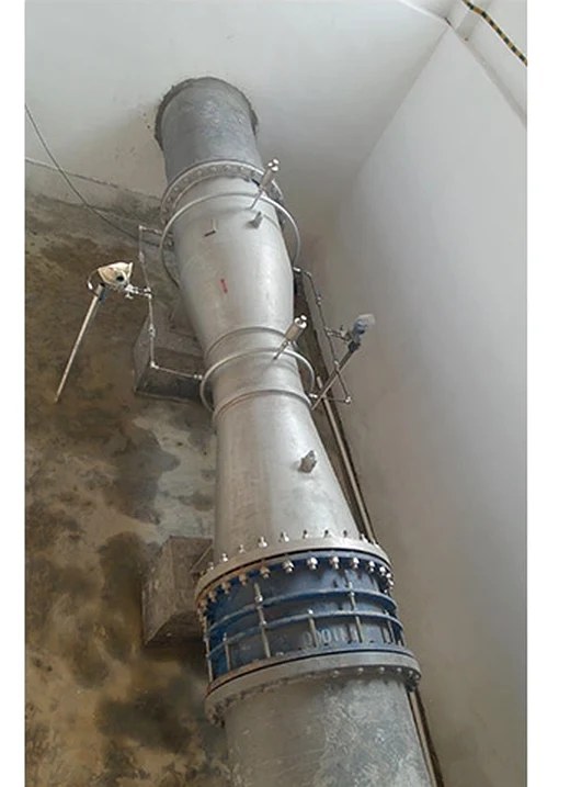
Oil and gas refinery, South America. A refinery specified a classical venturi tube on a DN100 (4 in) process line and asked for the basic dimensional drawing to accompany the quotation, with the sizing calculation to follow. We supplied a machined classical venturi with its dimensioned drawing and a β and discharge-coefficient sheet tied to the line data. That let the piping group set the meter run before the calculation book was finalized. The result was a primary element the customer could fabricate around without waiting on paperwork.
Installation and taps
A venturi is forgiving compared with an orifice, but it still needs straight pipe: about 5 D upstream of a single 90-degree elbow, 10 D upstream of two elbows in perpendicular planes, 20 D downstream of a partly closed valve, and 4 D of straight run downstream before the next disturbance. Tap orientation depends on the fluid, and getting it wrong gives you either a slugged transmitter or a water-logged impulse line.
| Fluid | Tap position on a horizontal pipe |
|---|---|
| Clean liquid | Taps at 3 and 9 o’clock, so gas cannot collect in the impulse lines |
| Gas, possible condensate | Taps at 12 o’clock, so condensate drains back to the pipe |
| Steam | Taps at 3 and 9 with condensate pots below and equal leg lengths |
The taps themselves are the usual failure point. On scaling water or slurry they plug with debris and bias the reading low, so plan a yearly throat inspection and use the flush connections most venturis provide. A three-valve manifold at the transmitter lets you zero and service it without losing the line.
Venturi flow meters
Instranova builds classical and short-form venturi flow meters from DN50 to DN1200 in carbon steel and stainless, as one of the primary elements in our differential-pressure flow meter range. To size one, we work from the line data, not a catalog number. Send these five points and we return a β ratio, a differential span, and a dimensioned drawing:
- Pipe size, schedule, and material
- Fluid, density, and viscosity at operating conditions
- Design, minimum, and maximum flow
- Operating pressure and temperature
- Accuracy target and any standard you must meet (ISO 5167-4 or ASME MFC-3M)
FAQ
What is a venturi tube used for?
Measuring flow rate by sensing the pressure drop across a constricted throat. Common industrial uses are municipal water mains, power-plant feedwater, chilled-water HVAC, and oil custody-transfer headers, wherever the low permanent pressure loss of a venturi is worth its higher cost. The same shape also entrains air in eductors and gas-grill burners, but those are not flow measurement.
How does a venturi tube work?
Fluid accelerates through a converging cone, which drops the static pressure at the throat by Bernoulli’s equation. A differential pressure transmitter reads the difference between an upstream tap and a throat tap, and the volumetric flow comes out proportional to the square root of that differential.
What is the difference between a venturi tube and an orifice plate?
Both create a differential for flow measurement. A venturi recovers most of the pressure, with 5 to 20 percent permanent loss, thanks to its diverging cone. An orifice plate dumps 40 to 95 percent as turbulent loss. A venturi costs several times more but pays it back in pump energy on large continuous lines.
What pressure recovery does a venturi tube achieve?
About 80 to 95 percent of the differential pressure is recovered as static pressure downstream, depending on the beta ratio and the divergent cone angle. A beta 0.7 tube with a 7-degree cone recovers roughly 95 percent, while a beta 0.4 tube at 15 degrees recovers about 80 percent.
Request a quote
Tell us the application and we size one venturi to your line data, not a shelf part. Reach our application engineers or use the form below with your pipe size, fluid, design flow, and operating pressure and temperature. We typically reply within one business day.
Written and technically reviewed by Wu Peng and the Instranova engineering team.