By Wu Peng, Senior Process Instrumentation Engineer · Last reviewed July 15, 2026
The K-factor of a flow meter is the number of output pulses the meter generates per unit of fluid volume, stated as pulses per gallon or pulses per liter. Divide the pulse frequency by the K-factor and you have the flow rate; count the pulses and divide by K and you have the total volume passed. Every turbine, paddle wheel, oval gear, and vortex meter with a pulse output carries one, printed on its calibration certificate. This guide gives the formula, typical K-factor ranges by meter type and size, worked calculations in both per-second and per-minute form, and the field procedure for checking a K-factor when the certificate is missing or the meter has drifted.
Contents
- K-factor defined
- K-factor formula and units
- K-factor chart
- Entering the K-factor
- Frequency to flow rate
- K-factor calibration
- K-factor drift
- K-factor vs meter factor
- Common K-factor mistakes
- Other K-factors
- Pulse-output flow meters
- FAQ
K-factor defined
A pulse-output flow meter converts fluid motion into an electrical pulse train. In a turbine meter each rotor blade passing the magnetic pickup makes one pulse; in a vortex meter each shed vortex makes one; in an oval gear meter each rotation passes a fixed swept volume of liquid. The K-factor is the calibration constant that ties that pulse train back to real volume:
K = pulses ÷ volume
A meter tagged K = 2,400 pulses per liter produces 2,400 pulses for every liter that passes. The receiving instrument, whether a flow transmitter, totalizer, batch controller, or PLC counter card, needs this number to turn raw frequency into GPM, L/min, or m3/h. Meters with only an analog 4-20 mA or 0-5 V output do the conversion internally, so the K-factor never leaves the factory paperwork. Any meter you read through its pulse channel needs the K-factor entered at your end.
K-factor formula and units
Two forms of the same constant cover everything you will do with it. The defining form comes from calibration, where N pulses are counted while a known volume V passes:
K = N ÷ V (pulses per unit volume)
The working form converts frequency to flow. On a per-second basis, frequency f in Hz divided by K in pulses per liter gives liters per second. Because plant flow units run in minutes and hours, the practical version carries a time factor:
Q = f ÷ K (L/s) or Q = f × 60 ÷ K (L/min or GPM, matching the K unit)
The K unit must match the volume unit of the answer. The common ones:
| K-factor unit | Where you meet it |
|---|---|
| pulses/liter | SI default on most European and Asian meters |
| pulses/gallon (US) | US default; confirm US vs imperial gallon on legacy UK specs |
| pulses/m3 | Utility-scale water and gas meters |
| pulses/ft3 | US gas meters |
Converting between them is one multiplication: pulses/gal = pulses/L × 3.785, because a US gallon is 3.785 liters. A meter tagged K = 2,400 pulses/L is the same meter as one tagged K = 9,085 pulses/gal. Enter the gallon figure into a totalizer configured for liters, though, and every reading is wrong by that same 3.785 factor. If your process figures and datasheet speak different flow units, the flow rate units guide has the full conversion set.
K-factor chart
Typical K-factor ranges by meter type and line size, in both unit systems. Treat these as sanity-check figures only: the calibration certificate wins, and designs differ enormously between manufacturers. A 2 inch turbine can carry anything from about 50 to about 2,000 pulses per gallon depending on blade count and pickup design.
| Meter type | Size | K-factor (pulses/L) | K-factor (pulses/gal US) |
|---|---|---|---|
| Turbine, liquid | DN15 (1/2 in) | 10,000-30,000 | 38,000-113,000 |
| Turbine, liquid | DN25 (1 in) | 1,500-3,000 | 5,700-11,400 |
| Turbine, liquid | DN50 (2 in) | 200-500 | 760-1,900 |
| Turbine, liquid | DN100 (4 in) | 20-60 | 76-227 |
| Turbine, gas | DN50-DN150 | 10-200 | 38-760 |
| Vortex | DN25 | 200-400 | 760-1,515 |
| Vortex | DN50 | 30-80 | 114-300 |
| Vortex | DN150 | 2-6 | 7.6-23 |
| Paddle wheel | DN15-DN50 | 50-2,000 | 190-7,600 |
| Oval gear (PD) | DN15 | 1,000-5,000 | 3,800-19,000 |
| Oval gear (PD) | DN50 | 50-200 | 190-760 |
K falls steeply as line size grows, roughly with the cube of the bore for turbines, because a larger rotor turns fewer revolutions for the same delivered volume. That is why a DN15 turbine can run tens of thousands of pulses per liter while a DN150 vortex fires single digits. Neither figure is better; what matters is where the resulting frequency lands, covered next.
Entering the K-factor
The certificate states K in pulses per volume. Receiving instruments accept it in one of two conventions, and mixing them up is a classic commissioning error:
- Pulses per unit volume. Modern totalizers and flow computers ask for K exactly as printed, say 9,085 pulses/gal, then handle the time base themselves whether the display is set to GPM or gallons total.
- Scaled for the time base. Some rate indicators ask for the factor that maps input frequency in Hz directly to the display unit. For a GPM display that entry is K ÷ 60: a 9,085 pulses/gal meter is entered as 151.4. The manual, not habit, tells you which convention the instrument uses.
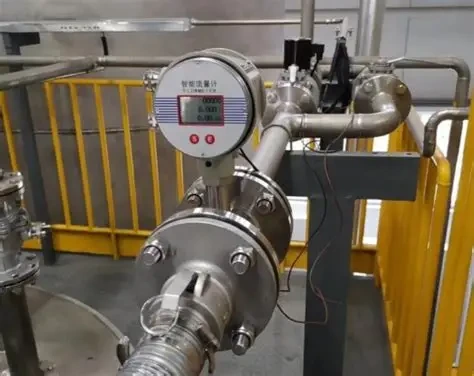
Electronic meters blur the picture in the other direction. A magnetic flow meter converter generates a scaled pulse output where the pulse weight is programmed, for example one pulse per 10 liters, rather than fixed by rotor geometry. Note the inversion: a pulse weight is volume per pulse, a K-factor is pulses per volume, so one pulse per 10 liters is the same information as K = 0.1 pulses/L written the other way up. Set it in the converter menu and program the receiving counter with the matching convention.
Frequency to flow rate
A worked example, end to end. A DN25 liquid turbine meter carries a certificate K-factor of 2,400 pulses/L and the counter reads 2,666.7 Hz.
- Per-second form: Q = f ÷ K = 2,666.7 ÷ 2,400 = 1.111 L/s.
- Per-hour: 1.111 × 3,600 = 4,000 L/h = 4 m3/h.
- In US units: K = 2,400 × 3.785 = 9,085 pulses/gal, so Q = 2,666.7 × 60 ÷ 9,085 = 17.61 GPM. The same flow either way: 4 m3/h is 17.61 GPM.
- Totalization: each pulse is 1/2,400 of a liter, 0.417 mL, so the count itself is the volume record.
Run your own numbers in the K-factor calculator: it converts frequency and K to flow in four units, derives K from a pulse count and volume, and corrects an existing K against a proving measurement.
Check the frequency window while you are at it. Pulse inputs typically accept about 1 Hz to 10 kHz. A DN15 turbine at K = 30,000 pulses/L outputs 8,333 Hz at 1 m3/h, fine, but 16,667 Hz at 2 m3/h, beyond many inputs. At the other end, a DN150 vortex at low flow can drop below a few hertz, where rate displays get jumpy. Match the K-factor and the flow range to the receiving instrument before ordering, not after.
K-factor calibration
When the certificate is lost, the meter has been rebuilt, or billing disputes start, measure K directly against a reference volume:
- 1. Run the meter into a calibrated vessel, weigh tank, or in series with a trusted reference meter, at a stable flow near the middle of the meter’s linear range.
- 2. Count total pulses N over the delivered volume V; collect for at least 60 seconds so start and stop errors wash out.
- 3. K = N ÷ V. Example: 12,540 pulses while 250.0 L is delivered gives K = 50.16 pulses/L.
- 4. Repeat 3 to 5 times and average. Spread above about half a percent points to unstable flow or air in the line, not the meter.
A multimeter with a frequency function gives a faster sanity check when you only suspect the entry, not the meter. Compute the frequency you should see at a known flow, f = Q × K ÷ 60 with Q in GPM and K in pulses/gal, then read the actual Hz across the pulse output: 20 GPM through a 300 pulses/gal meter should show 100 Hz. A reading off by more than about 5% points to a wrong K entry, electrical noise coupled into the signal wiring, or a missing pull-up resistor on the pickup, not necessarily a worn meter.
If a K-factor is already entered and the totalizer simply disagrees with a known delivery, correct it proportionally: new K = old K × metered volume ÷ actual volume. A totalizer showing 5.20 gal for a true 5.00 gal delivery with K = 76.0 entered needs K = 76.0 × 5.20 ÷ 5.00 = 79.04. That is a 4.0% over-registration, which no plant wants on an invoice. Formal calibrations for fiscal service follow ISO 4185 (weighing method) or API MPMS Chapter 5.3 for turbine meters, with 5 to 7 points across the turndown and a linearization curve stored in the flow computer.
K-factor drift
A K-factor is measured on a specific fluid at a specific condition, and three things move it in service:
- Viscosity. Turbine meters are calibrated on water unless you ask otherwise. A thicker fluid drags the rotor, lowering the frequency at a given flow, and shifts K by a few percent depending on the meter. Running diesel, glycol, or oil against a water calibration is the single most common hidden error; order a viscosity-specific calibration for anything far from 1 cSt.
- Bearing wear. Wear adds friction, the rotor lags, and indicated flow creeps low over months. This is the dominant drift term in turbine meters and the reason custody meters are recalibrated on a schedule: common practice is every 6 to 12 months for billing service, 1 to 2 years for process control, 2 to 3 years for non-critical monitoring.
- Flow profile. Swirl from a nearby elbow or valve loads the rotor unevenly and shifts the effective K. Respect the straight run requirements; a flow conditioner buys back most of the length where space is tight.
Vortex meters have no bearings, so their K-factor holds unless the bluff body scales, fouls, or chips; the shedding frequency follows a near-constant Strouhal number once Reynolds number is above the meter’s stated floor. That stability is a fair reason to pick a vortex flow meter for steam and gas service where a turbine would need frequent proving.
K-factor vs meter factor
Custody-transfer paperwork uses both terms and they are not the same thing. The K-factor is the pulses-per-volume constant discussed on this page. The meter factor is a dimensionless correction near 1.0, defined in custody practice as actual volume divided by meter-indicated volume, determined each time the meter is proved. The flow computer applies the meter factor on top of the nominal K-factor, so drift shows up as a meter factor walking away from 1.0000 between provings rather than as an edited K. If a document says “MF = 1.0026”, the meter under-reads by 0.26% and the computer scales it back up. Process installations without provers skip the meter factor and simply update K at recalibration.
Common K-factor mistakes
| Mistake | What happens |
|---|---|
| Mixing pulses/gal and pulses/L | Every reading wrong by 3.785×. Check the transmitter volume unit against the K unit before commissioning. |
| Entering per-volume K where the instrument wants per-minute scaling | Display reads 60× low (or high). The 9,085 vs 151.4 convention above; the instrument manual decides. |
| Trusting the K printed on the meter body | Nameplate K may be nominal or superseded by a later calibration. Use the current certificate, and after any field correction, record the new value on the tag. |
| Copying K from a sister meter | Two meters of the same model differ by percent-level amounts; two sizes differ by an order of magnitude. Each serial number has its own K. |
Other K-factors
Three unrelated quantities share the name, and search results mix them freely. Fire sprinkler K-factor sizes a nozzle: Q = K × the square root of pressure, no pulses involved. HVAC duct and VAV K-factors scale a velocity-pressure reading into airflow. Sheet metal K-factor is a bend-allowance ratio in fabrication, typically 0.3 to 0.5, and has nothing to do with flow at all. If you arrived here for one of those, this page is the wrong K; everything above concerns pulse-output flow meters only.
Application example
Machine builder, India. An OEM skid needed a compact DN15 turbine meter for glycol and distilled water at 0.6 to 6 m3/h and 1.6 MPa, with a pulse-only output feeding the machine’s own controller. That architecture puts the K-factor workflow entirely on the customer’s side: the controller is programmed with the certificate K, and because glycol runs thicker than the water the meter is calibrated on, we quoted the meter with a fluid-matched calibration so the certificate K applies to the actual medium rather than to water. No display, no transmitter, one number to enter.
Pulse-output flow meters
Every pulse-output meter we ship carries its K-factor on the calibration certificate, with multi-point calibration available where the receiving system stores a linearization curve. The LWGY turbine flow meter covers DN2 to DN300 with a three-wire voltage pulse (high level 8 V or more, low level 0.8 V or less) alongside optional 4-20 mA and RS485; the cryogenic turbine version runs the same pulse architecture down to −196 C for LN2 and LOX. For high-viscosity liquids where a turbine’s K would wander, the oval gear flow meter gives a displacement-fixed pulse instead. Browse the full turbine series and vortex series for pulse specifications by model, or measure mass directly with a Coriolis mass flow meter, whose reading does not hang on a rotor’s K-factor at all.
FAQ
What is the K-factor in a flowmeter?
The K-factor is the calibration constant of a pulse-output flow meter: the number of electrical pulses the meter produces per unit of fluid volume, stated in pulses per gallon or pulses per liter. It is determined by calibration against a reference standard and printed on the meter’s calibration certificate. Dividing the output frequency by the K-factor gives the flow rate.
How do you calculate K-factor flow rate?
Divide the pulse frequency by the K-factor: Q = f ÷ K gives flow per second, and Q = f × 60 ÷ K gives flow per minute in the K unit’s volume. A meter with K = 150 pulses/gal reading 600 Hz is passing 600 × 60 ÷ 150 = 240 GPM.
How do you calculate the K-factor?
Count pulses over a known volume: K = N ÷ V. Deliver a measured volume from the meter into a calibrated vessel or against a reference meter at stable flow, total the pulses for at least 60 seconds, divide, and average 3 to 5 runs. To correct an existing K against a proving measurement, multiply the old K by metered volume over actual volume.
What’s a good K-factor?
One that puts the output frequency inside the receiving instrument’s input window, typically about 1 Hz to 10 kHz, across your whole flow range. Higher K gives finer totalization resolution but tops out the input sooner; lower K starves the rate display at low flow. K-factor magnitude says nothing about accuracy, which comes from the meter’s calibration and linearity.
What is the K factor in a magnetic flow meter?
On a magnetic flow meter the pulse output comes from the converter electronics, not from moving parts. The converter menu asks for a pulse weight, volume per pulse, which is the reciprocal of a K-factor: one pulse per 10 liters equals K = 0.1 pulses/L. The receiving counter must be programmed with the matching value, but unlike a turbine’s K it is chosen at commissioning rather than fixed by geometry.
Request a quote
Send us the fluid, viscosity, line size, flow range, and what the pulse signal feeds, and we will size the meter, match the K-factor and output level to your counter’s input spec, and calibrate on a fluid that behaves like yours. Tell us the application and we configure one unit, not a shelf part.
Written and technically reviewed by Wu Peng and the Instranova engineering team. Worked figures are computed from the exact US gallon definition (3.785411784 L); calibration practice references ISO 4185 and API MPMS Chapter 5.3. Questions? Reach our application engineers.