Home › Level Instruments › Magnetic Level Gauge
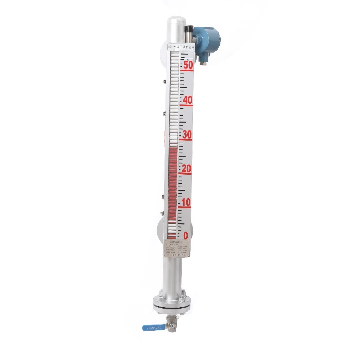
Magnetic Level Gauge (UHZ Series Bypass Indicator)
The UHZ magnetic level gauge reads liquid level from the outside of a vessel. A magnetic float sealed in a bypass chamber flips a bi-color flap column, red below the liquid and white above, so the level is visible across the plant with nothing touching the process and no glass to break. A 4–20 mA transmitter and switches clamp on without breaking the seal.
- Range: 0 to 12 m; display accuracy ±10 mm
- Process: -120 to 450 °C; to 16 MPa (by type)
- Wetted: stainless steel, PVC, or Ti
- Types: standard, anti-corrosive, heat-traced, high-temp, high-pressure, flameproof, top-mounted
- Add-ons: 4–20 mA / HART transmitter, reed switches, Ex d / Ex ia
A magnetic level gauge, also called a magnetic level indicator or bypass level gauge, is the modern replacement for a tubular sight glass. It is what most oil, gas, and chemical plants now use above about 150 psi, or whenever the fluid is toxic, flammable, or opaque. The level shows on a bright bi-color flap column on the outside of a sealed metal chamber, so an operator reads it from across the plant, and a transmitter or switches can be added later without opening the process.
Overview
The UHZ series gauge is a bypass chamber piped into the vessel through flanges, so the liquid inside it sits at the same height as the tank. A float carrying a magnet rides on that surface, and its field passes through the non-magnetic chamber wall to flip an external flap column: red below the liquid, white above. Because the indicator and any transmitter sit outside the pressure boundary, they never touch the medium. The chamber is built to the height of the vessel, the range runs from 0 to 12 m, and a family of types covers atmospheric to 16 MPa and -120 to 450 °C. For a continuous electronic reading on the same chamber, add a clamp-on magnetostrictive level transmitter.
Features
What sets the UHZ magnetic level gauge apart from a sight glass and from electronic gauges:
No process seal to leakThe float and magnet are sealed in the metal chamber and the readout never touches the medium, so there is no glass to shatter and no leak path. Few sealing faces, safe and reliable.
Clear, long-distance readingThe bi-color flap column, red below and white above the surface, is intuitive and visible across the plant, where a tubular sight glass forces you to stand at the tank.
Works with no powerThe flap column is purely magnetic and mechanical, so it keeps showing level during a power outage and needs no calibration to read. The indicator is fully isolated from the medium.
A type for every serviceStandard, anti-corrosive, heat-traced, high-temperature (to 450 °C), high-pressure (to 16 MPa and beyond), flameproof, and top-mounted versions, in stainless steel, PVC, or titanium.
Clamp on a transmitter, liveA 4–20 mA / HART transmitter or reed-switch alarms clamp to the chamber outside the seal, and can be added or removed in service.
Replaces a sight glassFor fluids above about 150 psi, or toxic, flammable, or opaque media, where a glass gauge is unsafe or unreadable.
Working principle
Three physical principles work at once. By communicating vessels, the bypass chamber is piped into the tank through flanges, so the liquid in it equalises with the tank level. By Archimedes buoyancy, the float is density-matched to ride exactly on the liquid surface, not in the vapor or submerged. By magnetic coupling, a magnet set at the float’s waterline turns each flap of the external column 180 degrees as it passes. Each flap is half red and half white, so it shows red below the liquid and white above; the color boundary is the level. The chamber wall is non-magnetic, so the field reaches the flaps while the pressure boundary stays sealed, and nothing on the indicator or transmitter touches the process.
UHZ types and selection
The UHZ family scales the chamber, materials, and rating to the service. Pick the type by the temperature, pressure, and medium; the float, flanges, and range are then built to the vessel.
| Type | Best for | Pressure | Temperature |
|---|---|---|---|
| UHZ-P Standard | Local display on open or pressurised vessels | to 1.0 MPa | to 80 °C |
| UHZ-F Anti-corrosive | Corrosive or toxic media (PVC / PTFE wetted) | to 1.6 MPa | to 80 °C |
| UHZ-R Heat-traced | Viscous or hot/cold media (with heat tracing) | to 10 MPa | to 200 °C |
| UHZ-T High-temperature | Hot liquids, 200 to 450 °C | to 10 MPa | 200 to 450 °C |
| UHZ-Y High-pressure | Sealed vessels above 10 MPa | 10 to 20 MPa | below 200 °C |
| UHZ-H High-temp + high-pressure | Hot, high-pressure sealed vessels | 10 to 20 MPa | 200 to 450 °C |
| UHZ-B Flameproof | Hazardous areas, with 4–20 mA or alarms | to 10 MPa | to 120 °C |
| UHZ-D Top-mounted | Buried or underground tanks, read at grade | to 1.6 MPa | to 80 °C |
Technical specifications
| Parameter | Specification |
|---|---|
| Measuring range | 0 to 12 m (built to the vessel; sectioned for tall tanks) |
| Display accuracy | ±10 mm |
| Process pressure | 1.0, 2.5, 4.0, 6.4, 10.0, 16.0 MPa (to 20 MPa on high-pressure types) |
| Process temperature | -120 to 450 °C (type-dependent) |
| Medium density | ≥ 0.5 g/cm³ |
| Medium viscosity | ≤ 0.05 Pa·s |
| Wetted material | Stainless steel, PVC, Ti, or other on request |
| Indicator | Bi-color flap column: red below, white above the liquid |
| Alarm switch | AC 220 V 0.2 A / 110 V 0.5 A; NO or NC; over 100,000 cycles |
| Transmitter output | 4–20 mA / HART; DC 24 V; accuracy ±1% to ±2% of range |
| Explosion protection | Ex d IIC T6 (flameproof) or Ex ia IIC T6 (intrinsically safe) |
| Process connection | Flange (side/side or top), to the piping standard |
Ordering code
A UHZ order code combines the type, the process pressure, the medium density band, the display mode, any alarm points, and the range. For example, UHZ-F5602b 1200(L) is an anti-corrosive gauge for a medium density of 0.9–1.0 g/cm³ at 10 MPa, a 1200 mm range, a 316L body, with a continuous 4–20 mA output. Tell us the service and we return the full code with the build.
Transmitter and switches
Because the float carries a magnet, you can pick up its position electronically from outside the chamber, with no wetted parts and nothing breaking into the process. A 4–20 mA / HART transmitter clamps to the chamber for a remote, logged level on the control system, powered from DC 24 V. Reed-switch alarms clamp on at high, low, high-high, and low-low points with a normally open or normally closed contact rated AC 220 V 0.2 A and over 100,000 operations. A guided wave radar can also run in parallel on the same chamber for redundant measurement. Note that a clamp-on transmitter’s electronics limit the medium temperature to about 100 °C unless a cooling extension is fitted; the visual flap column still covers the full temperature range.
Magnetic level gauge vs sight glass
A magnetic level gauge is the modern replacement for a tubular or reflex sight glass, and it is why most plants switched above about 150 psi or on toxic, flammable, or opaque fluids. The difference is mainly safety and readability.
| Criterion | Magnetic level gauge | Tubular / reflex sight glass |
|---|---|---|
| Pressure boundary | Metal chamber, matched to the piping rating | Glass, can shatter; needs a gauge-glass class per ASME |
| Readability | Visible across the plant (red / white flap contrast) | Read only by standing at the tank |
| Process seals | Zero moving seals on the process side | Gasket and glass-to-metal seals to maintain |
| Outputs | Add a 4–20 mA transmitter and switches | Visual only |
| Fouling | Chamber is bypassed; no fouling on the readout | Glass fouls and needs cleaning to read |
Applications
UHZ magnetic level gauges are used across petroleum refining, municipal and water treatment, food, chemical, pharmaceutical, power, paper, metallurgy, marine, and boiler service: on boilers and deaerators, oil and gas separators, LPG and ammonia bullets, reactors and day tanks, and any toxic, flammable, or opaque liquid where a sight glass is unsafe. They are also chosen where a power-free, visible local indication has to stay readable during an outage, and where a transmitter may be added later.
Challenge: A user with portable cryogenic (liquid nitrogen) tanks needed a level readout that could be checked by eye, with no power and no calibration, on a sealed low-temperature vessel.
Solution: A magnetic level gauge, whose float and flap column carry no electronics, reads the level visually through the sealed chamber wall.
Result: A clear local level on each tank that works during an outage and needs no power, with the option to clamp on a transmitter if remote monitoring is added later.
Related products
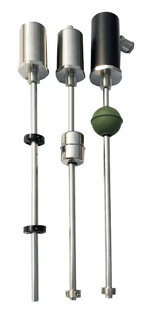 Magnetostrictive Level Transmitter
Clamp-on 4–20 mA output, ±0.05% FS.
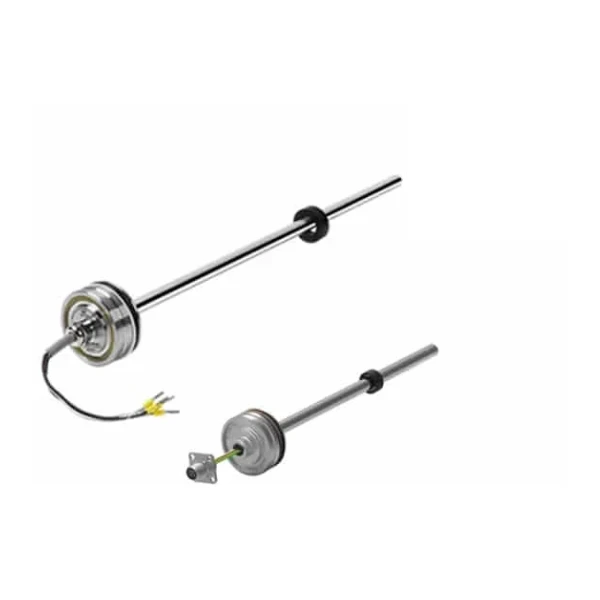 Hydraulic Cylinder Position Sensor
Magnetostrictive in-cylinder linear position sensor: absolute piston stroke, 350/700 bar, analog / SSI / CANopen.
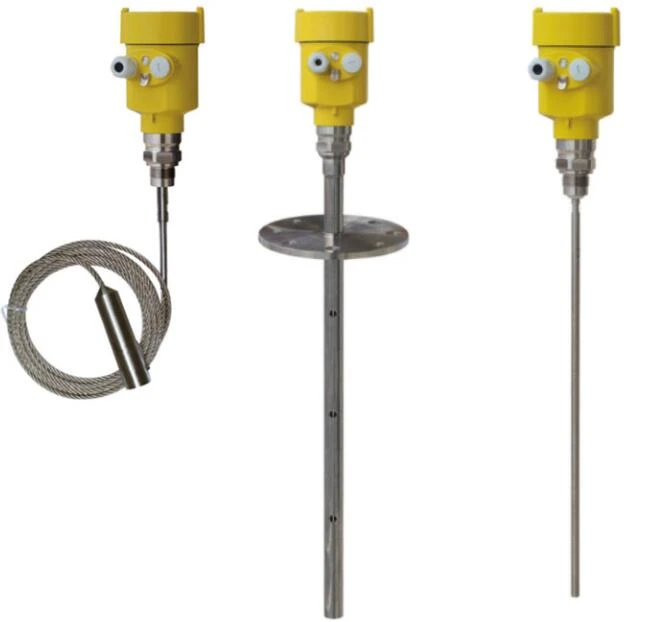 Guided Wave Radar
Parallel on the chamber for redundancy.
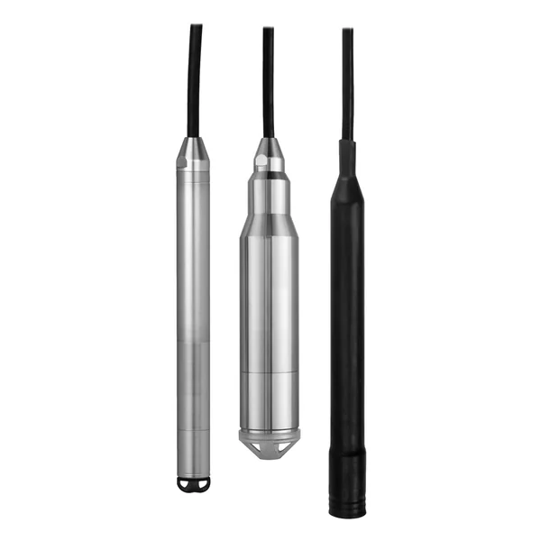 Hydrostatic Level Transmitter
Continuous level from the head of liquid.
Browse all level instruments →
FAQ
How does a magnetic level gauge work?
A bypass chamber is piped into the vessel at two points, so the liquid in it sits at the tank level. A float carrying a magnet rides on that surface, and its field passes through the non-magnetic chamber wall to flip an external flap column: red below the liquid, white above. You read the level from the colored column outside the sealed chamber, so nothing touches the process.
How do you calibrate a magnetic level gauge?
The visual flap column needs no calibration: the flaps track the float mechanically. What you verify is the zero and span of any clamp-on transmitter. The zero is the center of the lower flange, and the range is the center distance between the two flanges; set the transmitter’s empty and full points to that, then confirm two known levels against the flap column. A flap that reads wrong is usually a stuck flap or a sunk float, not a calibration fault.
How do you read a magnetic level gauge?
Read the color boundary on the flap column: the level is where the red (below the liquid) meets the white (above). The scale beside the column gives the height directly, and the contrast stays readable from across the plant. For a remote or logged reading, take the 4–20 mA signal from a clamp-on transmitter on the same chamber.
Request a quote
Tell us the vessel height, the liquid and its density, the process temperature and pressure, and the flange rating, plus whether you need a transmitter or switches. We build the chamber and indicator to the vessel, not a shelf part. Pricing and lead time follow by return email.