Home › Products › Level Instruments › Hydraulic Cylinder Position Sensor
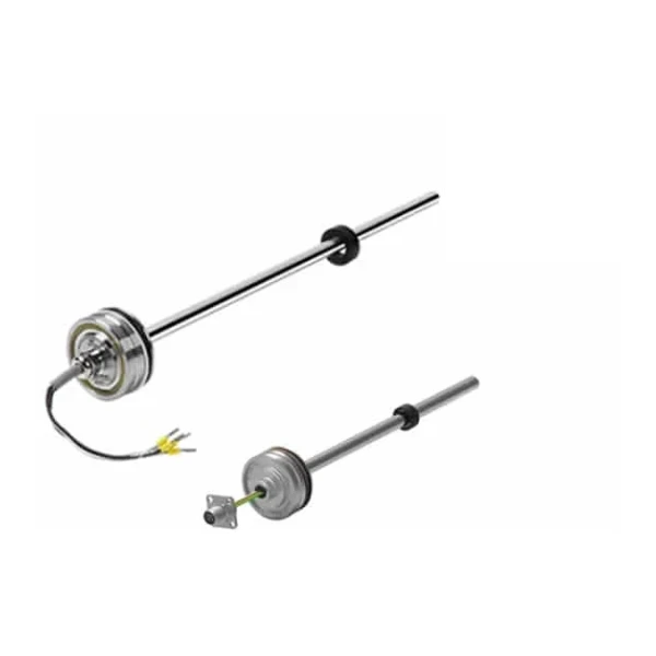
Hydraulic Cylinder Position Sensor (Magnetostrictive)
A hydraulic cylinder position sensor is a magnetostrictive linear displacement sensor built to fit inside a cylinder. A rod runs in the bore of the piston, a magnet rides with the piston, and the sensor reports the piston’s absolute position contactlessly. Because it is built into the cylinder and rated for 350 bar continuous / 700 bar peak, it gives stroke feedback for hydraulic and pneumatic actuators without an external linear scale.
- Stroke: 50 – 2500 mm (customized to the cylinder)
- Resolution / repeatability: ±0.1 mm; nonlinearity 0.02% (>400 mm)
- Output: 0.5–4.5 V, 4–20 mA, SSI, or CANopen
- Rating: 350 / 700 bar in cylinder; -40 to +105 °C; IP67
- Principle: magnetostrictive, contactless, absolute
Overview
The hydraulic cylinder position sensor replaces timed or proximity-switched motion with a continuous, absolute reading of where the piston is. The rod is drilled into the piston or mounted in the cylinder, a permanent magnet travels with the piston, and the electronics report position directly. There is no contact between the rod and the magnet, so nothing wears, and the position is absolute: after a power loss the reading is correct the instant power returns, with no re-homing.
It uses the same magnetostrictive technology as a magnetostrictive level transmitter, applied to a piston instead of a float. That makes it the right feedback device for closed-loop hydraulics in mobile machinery, presses, and industrial actuators, where stroke has to be known to a fraction of a millimeter.
Features
The reading is absolute, so the system knows the true piston position at power-up with no homing cycle or reference run.
The rod fits the cylinder bore and is rated 350 bar continuous, 700 bar peak, so the sensor lives inside the hydraulic pressure with no external scale to protect.
The position magnet never touches the rod, so there is nothing to wear over millions of strokes; repeatability stays at ±0.1 mm.
Pick a 0.5–4.5 V or 4–20 mA analog output, or a digital SSI or CANopen interface to match the controller.
-40 to +105 °C, IP67, with shock and vibration ratings and ISO 13766 / ISO 11452 EMC for on-vehicle use.
Measuring stroke from 50 mm to 2500 mm, customized to the cylinder, with the rod cut to the required length.
Working principle
Magnetostriction is the change in a material’s shape under a magnetic field. The sensor has a waveguide running the length of the rod. The electronics send a short current pulse down the waveguide; where the pulse meets the field of the position magnet, the combined fields twist the waveguide for an instant, launching a torsional strain wave back toward the head.
The electronics measure the time between sending the current pulse and detecting the returning strain wave. Because the wave travels at a fixed speed in the waveguide, that time is a direct, absolute measure of the distance to the magnet, and therefore the piston position. Nothing touches, the output is absolute, and the resolution holds to ±0.1 mm.
Technical specifications
| Parameter | Specification |
|---|---|
| Measurement | Linear displacement, absolute position |
| Measuring stroke | 50 mm to 2500 mm (customized) |
| Resolution | ±0.1 mm (50 – 400 mm); stroke / 4096 (> 400 mm) |
| Nonlinearity | ±0.1 mm (50 – 400 mm); 0.02% (> 400 mm) |
| Repeatability | ±0.1 mm |
| Update time | 2.0 ms; magnet speed unrestricted |
| Output | 0.5–4.5 VDC, 4–20 mA (and reverse), SSI, or CANopen |
| Power supply | 9 – 32 VDC |
| Operating temperature | -40 °C to +105 °C; temperature coefficient < 30 ppm/°C |
| Pressure rating (in cylinder) | 350 bar continuous; 700 bar peak |
| Shock / vibration | 100 g (11 ms); 25 g, 10 – 2000 Hz |
| Protection / EMC | IP67; CE, ISO 13766, ISO 11452 (mobile machinery) |
| Materials | 304 stainless steel housing and rod |
Representative specifications; confirm the exact stroke, output, and rod build against the datasheet for your cylinder.
Output and interface
The sensor matches the controller through one of four interfaces. Pick analog for a simple PLC or valve amplifier input, or a digital interface for a bus or a high-resolution closed loop.
| Output | Use it for |
|---|---|
| 0.5 – 4.5 V | Direct ratiometric input to a valve amplifier or analog controller |
| 4 – 20 mA | Noise-tolerant analog over longer cable to a PLC |
| SSI | Absolute digital position into a motion controller, no analog conversion |
| CANopen | On-vehicle bus on mobile machinery, several axes on one network |
Applications
The hydraulic cylinder position sensor gives stroke feedback wherever a piston position has to be known and controlled.
- Mobile machinery — boom, outrigger, and steering cylinders on cranes, excavators, and agricultural equipment, on a CANopen bus
- Presses — ram position for closed-loop force and depth control in hydraulic and forging presses
- Injection molding — clamp and injection position feedback
- Steel and metallurgy — roll-gap and caster cylinder position
- Industrial actuators — servo-hydraulic axes, dam and gate cylinders, test rigs
Challenge. A hydraulic press needed repeatable ram depth for closed-loop control, but its timed and limit-switch scheme could not hold the stop position as oil temperature and load changed through the shift.
Solution. A magnetostrictive position sensor built into the main cylinder fed absolute ram position to the controller, which closed the loop on measured position rather than on a limit switch, with the reading correct at every power-up.
Result. The ram stopped on a measured position with no homing cycle, and stroke feedback stayed within the sensor’s ±0.1 mm repeatability. (Representative application; stroke and tolerances are set per the cylinder.)
Related products
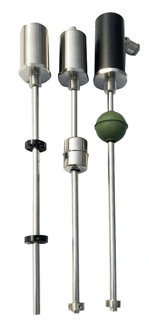 Magnetostrictive Level Transmitter
The same magnetostrictive principle applied to a tank float for high-resolution liquid level.
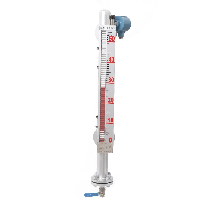 Magnetic Level Gauge
Magnet-coupled visual level gauge with an optional magnetostrictive transmitter.
FAQ
How does a magnetostrictive position sensor work?
The sensor sends a current pulse down a waveguide inside the rod. Where the pulse meets the field of a position magnet, the waveguide twists for an instant and launches a strain wave back to the head. The electronics time the round trip, and because the wave speed is fixed, that time gives the absolute distance to the magnet, and therefore the position. The measurement is contactless and absolute.
What is a hydraulic cylinder position sensor?
It is a magnetostrictive linear position sensor built to sit inside a hydraulic or pneumatic cylinder, rated for the cylinder pressure (350 bar continuous, 700 bar peak). The rod runs in the piston bore and a magnet rides with the piston, so the sensor reports piston stroke directly for closed-loop control, with no external scale exposed to the machine.
What output does an in-cylinder position sensor use?
Common outputs are 0.5–4.5 V or 4–20 mA analog for a PLC or valve amplifier, and SSI or CANopen for digital control. SSI gives an absolute digital position to a motion controller; CANopen suits mobile machinery where several cylinders share one bus. Choose the interface that matches your controller.
How is the sensor installed in a hydraulic cylinder?
The piston is drilled and a magnet is fitted to it, and the rod is mounted through the cylinder end cap so it runs in the piston bore as the cylinder strokes. The rod length is cut to the stroke. Because the rod sees full hydraulic pressure, the sensor is built and rated for it; confirm the rod build and mounting thread for your cylinder.
Request a quote
Send the cylinder stroke, the output you need (analog, SSI, or CANopen), the pressure rating, and the mounting and rod-end details. Our engineers confirm the build and return a quote.
About this page. Written by the Instranova engineering team. Specifications are representative; confirm the exact configuration against the datasheet for your application.