By Wu Peng, Senior Process Instrumentation Engineer · Last reviewed September 24, 2026
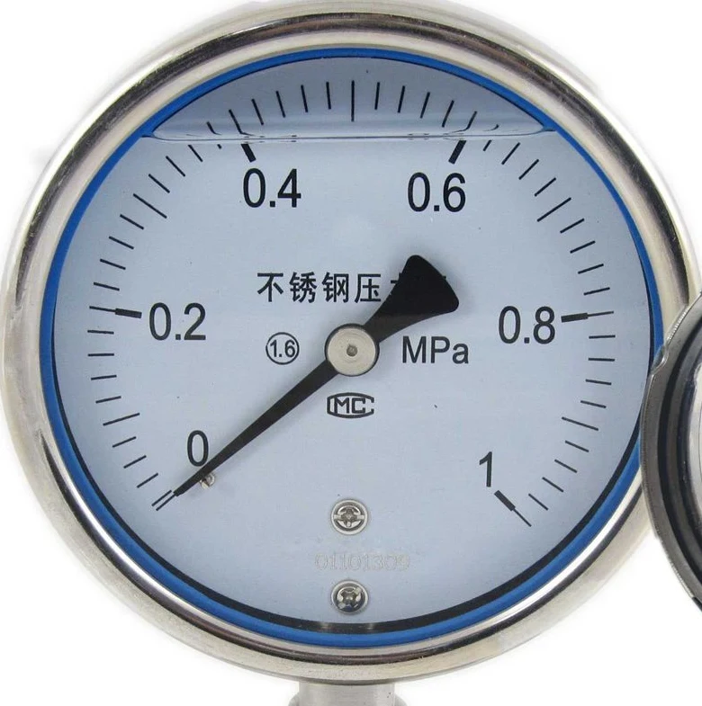
Pressure gauge calibration is a comparison: the gauge under test and a reference standard share one pressure source, and the difference between their readings is recorded at several points rising and falling. The acceptance limit comes from the accuracy class printed on the dial. A class 1.6 gauge with a 0 to 10 bar scale is allowed ±0.16 bar at every point; the reference should be at least four times better than that.
This guide walks through how to calibrate a pressure gauge on a bench. It covers the tolerance math, the reference equipment, how many points and cycles each class needs, a worked as-found table, and what belongs on the certificate. For the vocabulary of calibration versus adjustment versus verification, see the calibration terms guide. For transmitters and their trims, see the pressure transmitter calibration guide.
Contents
- Scope and terms
- Tolerance before pressure
- Reference equipment
- Points and cycles
- Bench setup
- Taking the readings
- Worked as-found table
- Adjust or replace
- Interval and records
- FAQ
Scope and terms
This page covers mechanical dial gauges: Bourdon tube, diaphragm and capsule types. The mechanics of the elastic element are on the Bourdon tube guide. How to read a dial correctly, including parallax and mirror bands, is on the pressure gauge reading guide. Electronic transmitters follow a different routine built around zero and span trims, covered separately.
Gauges serving code stamped boilers are also subject to statutory dial range rules, collected in the boiler pressure gauge guide.
Three terms organize the subject. Calibration is the documented comparison, with no change to the instrument. Adjustment is turning something so the gauge reads closer to true, and verification is the pass or fail decision against a stated tolerance.
A written pressure gauge calibration procedure keeps the three in that order: record as found first, decide pass or fail, and only then touch the pointer or the movement.
Tolerance before pressure
No reading means anything until the acceptance band is set, and the band comes from the accuracy class system the gauge was built to. EN 837-1 classes state one figure as a percentage of span, valid over the whole scale. ASME B40.100 grades 4A to 1A also apply one figure across the span. The letter grades A, B and C allow a tighter band over the middle half of the scale and a wider one in the first and last quarters.
| Gauge | Class or grade | Acceptance band |
|---|---|---|
| 0 to 10 bar, EN 837-1 | Class 1.6 | ±0.16 bar (16 kPa, about 2.3 psi) at every point |
| 0 to 100 psi, ASME | Grade 2A (0.5 percent) | ±0.5 psi at every point |
| 0 to 200 psi, ASME | Grade A (1-2-1) | ±2 psi from 50 to 150 psi, ±4 psi below and above |
Bands computed from the class definitions in EN 837-1 and ASME B40.100. The banded grades make the middle of the scale the place to judge a gauge, one more reason ranges are chosen so the working point sits there.
Write the band into the procedure in pressure units, not percent. A technician comparing 7.42 bar against 7.50 bar should be checking against 0.16 bar, not doing percentage arithmetic at the bench.
Reference equipment
Pressure gauge calibration equipment divides into the pressure source and the reference standard. On the source side, a hand comparator pump covers pneumatic work to a few tens of bar and hydraulic work into the hundreds. Screw-spindle hydraulic comparators reach 700 bar and beyond for high pressure gauge calibration. The reference side is either a digital reference gauge or a dead weight tester.
How much better the reference must be depends on whose rulebook you follow. United States practice, inherited from ANSI/NCSL Z540, asks for a 4 to 1 accuracy ratio. The German DKD-R 6-1 guideline works with one third of the tolerance, a 3 to 1 ratio. The EURAMET guidance for indicating gauges accepts a factor of 2 with a proper uncertainty budget.
The reasoning behind the ratios is on the transmitter calibration guide; the practical reading for dial work is simple. For a class 1.6 gauge, 4 to 1 means a reference at 0.4 percent of span or better, so a 0.25 percent digital reference gauge qualifies with room to spare.
A dead weight tester generates pressure directly from calibrated masses on a piston of known area, at 0.015 percent of reading for a standard instrument. One correction matters: the masses press down with local gravity, which varies by about 0.5 percent between the equator and the poles and falls with altitude. A tester trimmed for another site can be off by more than a fine gauge class before the first weight is loaded. Order the weights for your latitude, or apply the correction the maker publishes.
Points and cycles
The number of test points scales with the class. The everyday scheme for industrial dial gauges is five points at 0, 25, 50, 75 and 100 percent of span, taken rising and then falling. DKD-R 6-1 formalizes this into three sequences, and the sequence also sets how many times the gauge is preloaded to full scale before the readings start.
| Accuracy of gauge | Points | Preloads | Series |
|---|---|---|---|
| Better than 0.1 percent | 9 | 3 | 2 up, 2 down |
| 0.1 to 0.6 percent | 9 | 2 | 2 up, 1 down |
| Coarser than 0.6 percent | 5 | 1 | 1 up, 1 down |
Sequences per DKD-R 6-1, points distributed evenly over the span. A preload is one excursion to full scale, held briefly, then vented.
The preloads have a mechanical purpose. An elastic element that has rested at zero reads differently on its first stroke than on its third. Exercising it to full scale two or three times, holding for about a minute and venting, settles the element into its working state. The falling series is what exposes hysteresis, the signature of friction in the movement, and a gauge can pass every rising point and still fail on the way down.
Bench setup
Mount the gauge in the orientation it will serve in, which for panel and pipe gauges means dial vertical. EN 837-1 allows a 5 degree change in position to shift the reading by up to half the accuracy class, which is 0.8 percent of span for a class 1.6 gauge. A gauge calibrated flat on a bench and installed upright can lose a meaningful part of its band to geometry alone.
Keep the reference and the test gauge at the same height when the medium is liquid. Half a meter of water column is 4.89 kPa, about 0.71 psi, enough to consume a whole class band on a low range gauge. With oil or water in the lines, a height offset becomes a fixed zero error in the data. Then close the system and watch the reading for a minute: a slow decay is a leak, and no point should be recorded while the source is still creeping.
Temperature gets one line in the record. Gauge classes are stated at a reference temperature, typically 20 °C; a hot workshop shifts both the elastic element and any liquid fill. Note the ambient on the certificate and let the bench stabilize after the gauge comes in from the plant. Media compatibility carries over from service: a gauge destined for oxygen service must never meet oil on a calibration bench.
Taking the readings
Dial gauges are read with least division arithmetic, so the cleanest technique reverses the roles. Adjust the source until the pointer of the test gauge sits exactly on a scale mark, then read the true value from the reference. The error at 5.00 bar indicated might be a reference reading of 4.93 bar; nobody has to interpolate between graduations on the coarser dial.
Approach each rising point from below and each falling point from above, without overshooting; a reversal inside a point mixes the two curves and hides hysteresis. Wait about 30 seconds before recording, longer at full scale. A light tap on the case before reading is legitimate. If the pointer jumps when tapped, the movement has friction, and the size of the jump is itself a diagnostic worth a note in the record.
Worked as-found table
Here is what the record looks like for a 0 to 10 bar class 1.6 gauge, acceptance ±0.16 bar. The pointer was set on each dial mark and the reference read out, rising then falling. These are worked numbers to show the format, not a reproduced certificate.
| Dial (bar) | Ref rising | Error | Ref falling | Error | Verdict |
|---|---|---|---|---|---|
| 0.00 | 0.00 | 0.00 | — | — | Pass |
| 2.50 | 2.46 | +0.04 | 2.41 | +0.09 | Pass |
| 5.00 | 4.93 | +0.07 | 4.88 | +0.12 | Pass |
| 7.50 | 7.42 | +0.08 | 7.36 | +0.14 | Pass |
| 10.00 | 9.87 | +0.13 | — | — | Pass |
Error = dial reading − reference, so a positive value means the gauge reads high. Largest error +0.14 bar, falling at 7.5 bar; rise-fall spread up to 0.06 bar; all inside the 0.16 bar band. After venting, the pointer returned to within 0.02 bar of zero.
This gauge passes, and the pattern is typical: errors grow toward full scale, and the falling errors sit above the rising ones because friction makes the movement lag behind falling pressure. Had the full scale point read 10.00 against a reference of 9.83, the error of 0.17 bar would fail the gauge and send it to the next decision. The rise-fall spread matters even inside the band, because friction grows with wear and a spread near the class limit will not survive the next interval.
Adjust or replace
A failed gauge offers fewer remedies than a failed transmitter. Many industrial gauges have an adjustable pointer or a micrometer pointer for zero, and some movements provide a span adjustment on the sector linkage. Zero errors that are uniform across the scale respond well.
Errors that grow nonlinearly, a pointer that will not return to zero, or heavy hysteresis point to a deformed element or a worn movement. Those call for replacement rather than repair at the bench.
The economics decide the rest. Recalibrating a utility grade gauge can cost more than the gauge, which is why low cost gauges are widely treated as replace-on-fail items. One large maker states plainly that recalibration expense may exceed the price of a new unit. Reserve bench time for process grade and test gauges where the class, the fitting or the documentation carries real value, and buy utility gauges with a fresh factory record instead.
Interval and records
No standard dictates a calibration interval for pressure gauges; ASME B40.100 defines construction and grades, and the interval is a decision left to the owner. Across the manufacturers and calibration providers surveyed for this guide, twelve months is the default starting point. Move it with the evidence. Gauges on pulsating or vibrating service, or any gauge that has seen an overpressure event, need a shorter cycle, while a gauge with two clean as-found results in a row can support a longer one.
A usable pressure gauge calibration certificate lists the as-found and, if adjusted, as-left data, the reference standard with its own traceable calibration, ambient conditions, and the measurement uncertainty. Read the uncertainty line critically: if it is not comfortably smaller than the acceptance band, the calibration cannot prove compliance, and the guard band logic on the calibration terms guide applies.
Application note
The 330 anonymized inquiries behind this site include no stand-alone dial gauge calibration job, and that absence is the lesson. Gauge calibration questions reach us as equipment questions, most concretely a 700 bar hydraulic comparator inquiry described on our Bourdon tube guide. In our inquiry log, the procedure stays in house and the purchase is the bench. When gauges are ordered with calibration certificates, that request belongs on the purchase order line.
FAQ
How do I calibrate a pressure gauge?
Mount the gauge upright on a comparator with a reference at least four times more accurate. Exercise it to full scale and back a few times, then record readings at five or more points rising and falling. Compare each error against the accuracy class band and document the results.
Does a pressure gauge need to be calibrated?
It depends on what the reading decides. Gauges behind safety, quality or custody decisions need scheduled calibration with records. Utility gauges that only give an operator a rough look are often replaced instead of calibrated, since no regulation forces an interval on the owner.
How do I know if my pressure gauge is accurate?
Quick checks first: a vented gauge should rest on zero, and a tap on the case should not move the pointer. The real answer is a comparison against a better reference at several points; the gauge is accurate if every error stays inside the class band on its dial.
What is the ISO standard for pressure gauge calibration?
There is no single ISO document for it. Laboratories accredit to ISO/IEC 17025, and calibration sequences follow guidelines such as DKD-R 6-1. The accuracy classes being verified come from EN 837-1 in Europe and ASME B40.100 in the United States.
Request a quote
Tell us the application and we configure the instrument, not a shelf part. We supply gauges to a stated class with factory calibration records, or a diaphragm sealed gauge where the medium demands it. Reach our application engineers or use the form below.
Written and technically reviewed by Wu Peng and the Instranova engineering team.