Flow Meters › Hydraulic Flow Meter
Hydraulic Flow Meter
A hydraulic flow meter measures oil flow in a fluid power system: on a test bench, in a power unit, or teed into a machine in the field. Flow is the reading that tells you whether a pump, motor, or cylinder is delivering, because pressure alone only reports the load.
The choice comes down to four things: where in the circuit the meter taps in, the working pressure at that point, the viscosity of the oil, and the accuracy the job needs. A spur gear meter covers high pressure and small flows, and an oval gear meter totals viscous oil on low-pressure lines. A turbine meter suits clean thin fluid at higher flow. A variable-area meter gives a rugged local readout for troubleshooting.
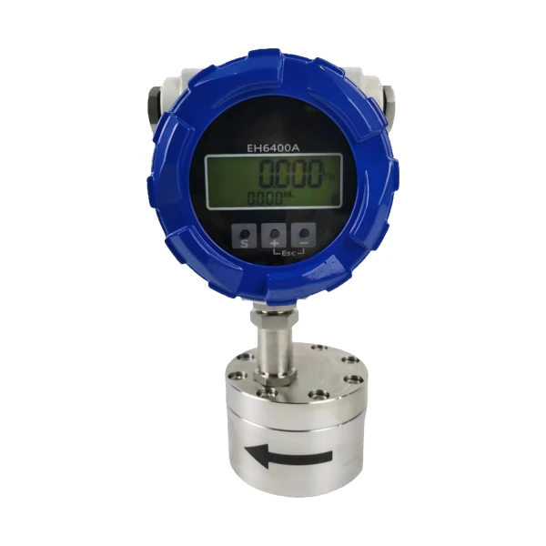 Gear Flow Meter
Spur-gear positive displacement for lube and hydraulic oil; micro flows from 0.1 L/h and pressure ratings to 40 MPa by model.
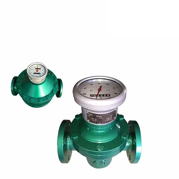 Oval Gear Flow Meter
Positive displacement for viscous oil on transfer and return lines; accuracy holds as the oil thickens.
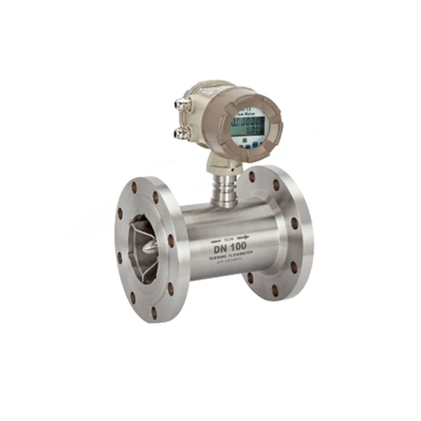 Turbine Flow Meter
For clean, low-viscosity fluid at higher flow; wide range at low cost when the oil stays near the calibration viscosity.
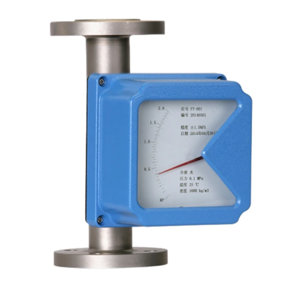 High Pressure Rotameter
Metal-tube variable area with a local dial; 4.0 MPa standard and high-pressure builds to 20 MPa, readable without power.
Choosing a hydraulic flow meter
All five technologies below meter hydraulic oil. They differ in pressure rating, in the viscosity window they read accurately, and in cost. The table gives the numbers; the sections after it explain the decisions behind them.
| Technology | Pressure rating | Viscosity | Accuracy | Choose it for |
|---|---|---|---|---|
| Gear (spur) PD | 1.6 to 40 MPa by model | Builds for thin (under 2 mPa·s) through high viscosity (200 mPa·s and up) | 0.5% of reading | Pressure-line taps, test benches, case-drain and small dosing flows from 0.1 L/h |
| Oval gear PD | 1.6 MPa; higher on request | To 2,000 mPa·s as a high-viscosity build; 5,000 by special order | 0.5% of reading; 0.2% option | Oil transfer, filling, and return-line totals |
| Turbine | To 6.3 MPa threaded; 25/42 MPa special builds | Clean, thin fluid near the calibration viscosity | 0.5% of reading; 0.2% option | Higher flows of thin, clean fluid at low cost |
| Variable area, metal tube | 4.0 MPa standard; 20 MPa high-pressure build; 25 MPa special | Float is sized for the stated fluid and viscosity | 1.5 or 2.5 grade | Local dial on power units and test points, no power needed |
| Coriolis | 4.0 MPa standard; builds to 30 MPa | Reads any viscosity; mass flow plus density | 0.1 to 0.5% | The tightest accuracy and direct mass flow |
The gear and oval gear meters both belong to the positive displacement line: each rotation sweeps a fixed volume, which is why thicker oil improves accuracy instead of degrading it. For oils and fluids well beyond hydraulic grades, see the high viscosity flow meter page.
Pressure rating and tap point
Industrial hydraulic systems commonly work between 10 and 40 MPa (1,450 to 5,800 psi) on the pressure line, and dedicated hydraulic test meters on the market are typically rated around 420 bar (6,000 psi) for that reason. Most general-purpose flow meters are not built for pressures anywhere near that, so the first decision is where the meter taps in.
On the pressure line the meter body must carry full system pressure. That is the case for our gear meter builds rated to 40 MPa, the high pressure rotameter to 20 MPa (25 MPa special), Coriolis builds to 30 MPa, and special turbine builds at 25 to 42 MPa.
On the return line the pressure has already dropped across the actuators to a few bar. An oval gear or turbine meter with a 1.6 to 6.3 MPa body is enough there, and it still totals the same circuit flow. The case drain runs near tank pressure and carries only leakage, which calls for a small meter, not a strong one. Tapping the return or the drain instead of the pressure line is the cheapest way to get a reading you can trust.
Viscosity and accuracy
Hydraulic oils are graded by viscosity at 40 C under ISO 3448: ISO VG 32 spans 28.8 to 35.2 cSt, VG 46 spans 41.4 to 50.6 cSt, and VG 68 spans 61.2 to 74.8 cSt. The viscosity the meter sees also moves with temperature, so the same VG 46 oil is far thicker at a cold morning start than at a 50 C working temperature.
That number decides the technology. A turbine meter is calibrated at one viscosity, commonly around 21 cSt on mineral oil. Manufacturers hold the added error to about 1% of full scale inside a band of roughly 18 to 26 cSt. Outside that band the reading drifts as the fluid drags on the rotor.
A positive-displacement meter behaves the other way around. Thicker oil seals the gear clearances better, so accuracy holds from thin flushing fluid up to 2,000 mPa·s and beyond. If the circuit runs one oil grade at a controlled temperature, a turbine is fine. If grades change, or the machine starts cold outdoors, pick a PD meter.
Sizing and pump diagnostics
Size the meter from the pump, not from the pipe. Theoretical flow is displacement times speed: a 100 cm³/rev pump driven at 1,450 rpm delivers 145 L/min (38.3 gpm) with zero wear. Choose a meter range that puts that figure well inside span rather than at the top of the scale.
The same meter then becomes a diagnostic tool. Measure delivered flow at working pressure and divide by theoretical flow: 131 L/min measured against 145 L/min theoretical is a volumetric efficiency of 90.3 percent. A common maintenance rule flags the pump for overhaul once volumetric efficiency falls below about 85 percent, and high-response servo circuits demand more.
On mobile machinery, an excavator or tractor circuit is checked the same way with a portable tester teed in at the pump outlet. Watching the case drain catches wear even earlier. On piston pumps and motors the leakage path grows before output flow visibly sags, so a small gear meter sized to the drain flow gives the first warning.
Oil cleanliness
Hydraulic contamination is stated as an ISO 4406 code, three numbers counting particles above 4, 6, and 14 microns. Circuits with servo valves are typically held to 16/14/11 or cleaner, and proportional-valve circuits to about 18/16/13. The target tightens as working pressure rises past roughly 21 MPa (3,000 psi).
The meter runs in the same oil. PD gear meters have close clearances and call for a filter upstream, and turbine bearings wear fast in dirty oil. Hold the ISO code at the level the most sensitive valve requires, and every meter in the table above is covered. On a system in unknown condition, meter the flow first and pull an oil sample at the same tap.
Cylinder testing
Cylinder and motor testing often needs flow read in both directions, and this is where a wrong meter gets expensive. A one-way meter with an internal check valve blocks reverse flow. Put one on the rod end of a double-acting cylinder and the trapped annulus side is pressure-intensified by the bore-to-annulus area ratio.
On a typical 2:1 cylinder the rod-end pressure can climb to about twice the relief valve setting, enough to burst fittings that were fine on the drive side. For pump and cylinder test work, state in the inquiry that the meter must pass or read reverse flow. Give the intensified pressure, not the pump pressure, as the rating.
Application note
Hydraulic repair and test benches. A typical bench meters each rebuilt pump at rated pressure before it ships: delivered flow against theoretical flow gives the volumetric efficiency that proves the rebuild. The meter tap sits on the pressure line, so the meter body, not just the plumbing, must carry the test pressure. The reading is compared cold and at working temperature, because the viscosity change moves marginal pumps across the pass line.
FAQ
What is a hydraulic flow meter?
A hydraulic flow meter measures the flow of oil in a fluid power system, usually in L/min or gpm, at pressures far above what general process meters carry. It is used to verify pumps, motors, and cylinders, to monitor case-drain leakage, and to meter oil transfer. Gear and oval gear positive-displacement meters, turbines, variable-area meters, and Coriolis meters all serve. The choice follows pressure, viscosity, and accuracy.
How to measure flow in a hydraulic system?
Tee a flow meter into the line you care about: the pump outlet for delivered flow, the return line for circuit totals, or the case drain for leakage. On a working machine the usual tool is a portable tester connected at the pump outlet. On a test bench or power unit a permanent meter with a pulse or 4-20 mA output feeds the readout or PLC. Always match the meter body rating to the pressure at that tap point.
How accurate are hydraulic flow meters?
Positive-displacement gear and oval gear meters hold about 0.5% of reading on oil, with 0.2% options. A turbine meter reads about 0.5% of rate while the oil stays near its calibration viscosity, and drifts outside that band. Variable-area dial meters are 1.5 or 2.5 grade instruments for local indication, and a Coriolis meter reaches 0.1 to 0.5% with direct mass flow.
What are the different types of hydraulic flow meters?
Four types cover almost all hydraulic work: positive-displacement meters (spur gear for high pressure and small flows, oval gear for viscous transfer), turbine meters for clean thin fluid, variable-area meters for local reading, and Coriolis meters for the tightest accuracy. The right one depends on the tap point pressure, the oil viscosity, and the accuracy the job needs.
Request a quote
Tell us where the meter taps in, the flow range, the working pressure at that point, and the oil grade and temperature. We size the meter, set the outputs, and confirm the pressure rating for the tap.