By Wu Peng, Senior Process Instrumentation Engineer · Last reviewed August 20, 2026
A transformer oil level indicator is a float-driven dial gauge mounted on the conservator or tank of an oil-filled transformer. The pointer moves between MIN and MAX marks as the insulating oil expands and contracts.
A reference mark shows where the pointer should sit at the filling temperature. Mineral insulating oil swells by roughly 0.75 percent for every 10 °C of temperature rise. The reading only means something when you know the oil temperature.
That last point is where most gauge readings go wrong. This guide covers how the magnetic gauge works, how to read it against the temperature marks, and the expansion math behind those marks. It then works through alarm contact ratings, gauge types and mounting, what a low reading means next to the Buchholz relay, and when a continuous level sensor is the better specification.
Contents
- How the gauge works
- Reading it correctly
- Oil expansion math
- Alarm contacts and outputs
- Gauge types and mounting
- Low oil decision rule
- Continuous level sensors
- FAQ
How the gauge works
The common dial instrument is the magnetic oil level gauge, often written MOG on substation drawings.
A float rides on the oil surface inside the conservator or tank. The float arm turns a bevel gear, and the gear turns a drive magnet inside the vessel. The magnetic field pulls a follower magnet on the outside. The follower carries the pointer.
The magnetic coupling is the central design decision. No shaft or gland passes through the vessel wall, so there is no seal to wear out and no leak path.
Manufacturer datasheets for DIN-pattern gauges rate the coupling tight to 10 bar. A cracked viewing glass therefore does not let oil out or moist air in. The same logic lets some gauges accept a replacement dial without lowering the oil.
Two float layouts exist. A radial float swings on a long arm from the end wall of the conservator, which suits long horizontal vessels. An axial float works where only a small float travel is possible.
On conservators fitted with a rubber air cell, the float rests on the cell instead of free oil. It follows the cell as it inflates and deflates. The pointer shaft can also carry one to three switch cams for alarms, which section four covers.
Reading it correctly
Every gauge face carries a reference mark, and the mark is not the same everywhere. Knowing which convention your dial follows is the first step in reading it.
| Reference mark | Where you see it |
|---|---|
| 25 °C | North American (ANSI) practice. Dials marked Low, 25 °C, High. The proper level when the oil sits at 25 °C. |
| +20 °C | IEC-pattern gauges. A common dial lettering is MIN, +20 °C, MAX; some dials add smaller tick marks in 5 or 10 °C steps. |
| 15 °C etch line | Some European sight glasses carry a single line etched at a 15 °C nominal level. Coarse; treat it as a check, not a measurement. |
| Fractional scale | Older dials read empty, 1/4, 1/2, 3/4, full with a separate filling curve on the nameplate or manual. |
The reference temperature is the oil temperature at which the pointer should sit on the mark, with the transformer de-energized at that temperature during filling.
The field rule is simple: compare the level gauge against the top-oil temperature gauge, not against the weather. A loaded transformer runs its oil well above ambient, so judging the level from the outside air temperature makes a correctly filled unit look overfilled. If the temperature implied by the pointer position roughly matches the top-oil gauge, the fill is right. A pointer implying a higher temperature than the oil gauge shows means too much oil; lower means too little.
Expect the pointer to sit below the reference mark on cold mornings and above it in summer load. Low-level alarms in sub-zero weather are a known and documented event; before treating one as a leak, check the oil temperature first. Section six gives the full decision rule.
Oil expansion math
Mineral insulating oil has a volumetric thermal expansion coefficient of about 7.2 to 8.0 x 10⁻⁴ per °C; 7.5 x 10⁻⁴ is a fair working value. That is the number behind every mark on the dial.
Delta V = V x 0.00075 x Delta T
A 2,000 L distribution transformer filled at 20 °C, running at 90 °C top-oil: 2,000 x 0.00075 x 70 = +105 L, a 5.25 percent volume gain
The same coefficient works in reverse: every 10 °C drop sheds about 0.75 percent of the oil volume. On a 40,000 L power transformer swinging from minus 25 °C standstill to 90 °C full load, the oil volume changes by about 3,450 L. That is why the conservator exists and why it is sized as a set fraction of the tank volume. The vessel must never overflow at the hottest condition, and never empty enough to draw air at the coldest.
Two practical notes. First, many transformer nameplates state the expected expansion per degree for that specific unit; use the nameplate figure over any generic coefficient when you have it.
Second, never top up a cold transformer to the reference mark. Oil filled to the 20 °C mark at 20 °C is correct. Oil filled to the same mark at 60 °C will push past MAX on the next hot day and can operate the pressure relief device.
Alarm contacts and outputs
A visual dial only helps when someone walks the yard. In a substation the gauge starts doing real protection work when its pointer shaft carries switch cams.
Typical builds fit one to three microswitches, factory-fixed or field-adjustable, wired as a low oil alarm and sometimes a second critical-low or high contact. IEC 60076-22-1 is the standard that covers these protective accessories. Read the contact ratings before wiring, because the two contact types behave very differently.
| Contact type | Rating (per IEC 60076-22-1 pattern datasheets) |
|---|---|
| Standard microswitch | 230 V AC: making 250 VA, breaking 60 VA. 24 to 220 V DC: making 130 W, breaking 25 W. Suits alarm panel relays and annunciators. |
| Gold-plated contact | Breaking about 6.9 VA max at 230 V AC (roughly 30 mA) or 6.6 W DC. For dry-contact PLC and RTU inputs only; switching heavier loads destroys the gold layer. |
Ratings above follow a published IEC-pattern gauge datasheet. Always confirm against the datasheet of the gauge you buy.
The wiring pattern that covers most substations is two potential-free contacts to the alarm panel. Each contact gets its own SCADA digital input so the operator sees which compartment alarmed.
Gauges are also available with a continuous output, 4-20 mA or RS485 Modbus RTU, which turns the dial into a trend. A slow gasket leak then shows up as a level curve that no longer tracks the daily temperature cycle. For what a 4-20 mA loop involves at the panel end, see our 4-20 mA current loop guide.
Gauge types and mounting
Three indicator types cover almost every transformer, and they are not interchangeable.
| Type | Where it fits | Limits |
|---|---|---|
| Magnetic dial gauge (MOG) | Conservator end or tank sidewall. Dial sizes run from about 100 to 250 mm (4 to 10 in) across manufacturers; readable from ground level. Takes alarm contacts and analog output. | Float can puncture, fill and sink, leaving a stuck low reading. Foam-filled floats avoid this. |
| Prismatic or tubular sight glass | Hermetic distribution transformers and small conservators. Direct optical reading, no moving parts, low cost. | No contacts, no remote signal, and a single etched line rather than a scale. A check, not an instrument. |
| Continuous level transmitter | Monitored fleets and unmanned sites. Magnetostrictive, float or capacitance sensors with 4-20 mA or Modbus into SCADA. | Needs a process opening and loop power; specified at build or during a monitoring retrofit. |
Mounting follows the tank design. Conservator transformers carry the gauge on the conservator end wall or shell, with inclined-mount variants (15, 30 or 45 degree) for angled end plates. Sealed and padmount transformers have no conservator at all. The gauge bolts to the tank sidewall at the design oil line, and a nitrogen blanket above the oil takes up the expansion, typically running between 2 and 5 psi when warm.
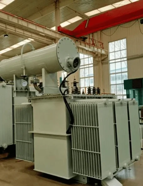
One detail worth knowing on air-cell conservators: the specification usually pairs two indicators. The magnetic gauge follows the air cell and reads the true oil level.
The separate sight window sits in the oil space and stays full at all times. The day that window shows a falling level is the day the cell has ruptured. The two instruments answer different questions, and neither replaces the other.
Low oil decision rule
Low oil causes damage in a fixed order. First cooling suffers. If the level drops below the radiator inlet, convection through the radiators stops, and the winding temperature climbs even though plenty of oil remains in the tank.
Then insulation: a further drop exposes energized parts designed to operate under oil, and the air gap invites flashover. Overfilling has its own failure list, from pressure relief operation to radiator damage on air-cell units. That is why the MAX mark matters as much as MIN.
The level gauge and the Buchholz relay split the protection work. The Buchholz relay sits in the pipe between tank and conservator and reacts fast to gas accumulation and oil surge from internal faults. The level gauge tracks slow, volumetric change: gasket weeps, a seeping radiator plug, seasonal contraction. Reading the two together gives a usable decision rule.
| What you see | Most likely meaning |
|---|---|
| Low-level alarm only, oil cold | Probably thermal contraction. Check top-oil temperature against the dial before calling it a leak; sub-zero false alarms are common. |
| Low-level alarm, oil warm, level trending down over days | Slow leak. Walk the gaskets, valves and radiator plugs; schedule a top-up with dry oil. |
| Buchholz gas alarm plus falling level | Real oil loss or an internal fault in progress. Treat as urgent; do not reset and wait. |
| Level frozen in one position for weeks | Suspect a stuck or sunken float. A healthy pointer moves with the daily temperature cycle. |
The last row is the argument for trending. A dial that never moves looks reassuring on a walkdown, but a level that ignores a 20 °C day-night swing is a failed float, not a stable transformer.
Continuous level sensors
For unmanned substations, generator step-up units and any site already running SCADA, a continuous sensor next to (or instead of) the dial turns oil level from a monthly note into a live trend. Three sensor types suit transformer oil.
A float level sensor with reed-chain output is the direct electronic cousin of the MOG float and handles point alarms plus a stepped continuous signal. A magnetostrictive level transmitter reads the same float to millimeter resolution, which suits the small level span of a conservator.
A capacitance level transmitter has no moving parts at all. Mineral insulating oil is a clean, stable dielectric at about 2.2 relative permittivity, the same low-dielectric situation we cover in the diesel tank level guide. A non-conductive fluid like oil is exactly where capacitance probes behave well. Browse the full range on our level instruments page.
When you ask for a quotation, five items settle the selection. They are vessel type (conservator, air cell or sealed tank), level span in mm, the process opening available, the output needed (contacts, 4-20 mA, RS485), and the ambient range at site. Oil type matters too; natural-ester fluids run higher viscosity but do not change the float or magnetostrictive selection.
Application note
Monitoring retrofit pattern. A typical specification we see for transformer oil monitoring pairs the existing dial gauge, kept as the local reading and alarm contact, with a continuous transmitter on a spare conservator opening. The transmitter is wired as 4-20 mA to the station RTU. The dial satisfies the walkdown, and the trend catches the slow leak between walkdowns (a typical configuration, not a specific customer project).
FAQ
How to check oil level on transformer?
Read the dial pointer against the reference mark, then read the top-oil temperature gauge. The two should agree: at 25 °C oil the pointer sits at the 25 °C mark, higher when hot, lower when cold. On sight-glass units, the oil band should cover the etched line at the nominal temperature. Log both readings together.
What is the proper oil level for a transformer?
The level that matches the current oil temperature on the filling curve. At the dial reference temperature (25 °C ANSI practice, +20 °C on IEC-pattern dials) the pointer should sit exactly on the mark. Across the design temperature range the pointer must stay between MIN and MAX. The nameplate often states the expansion per degree for that unit.
How can you tell if a transformer is oil filled?
Check the nameplate first: a liquid type entry and cooling class codes such as ONAN or KNAN mean liquid-filled. Visually, oil-filled units carry radiators or cooling fins, often a conservator on top, oil level and temperature gauges, and a drain or sampling valve. Dry-type transformers have ventilation grilles and none of those fittings.
What is the acceptable moisture level in transformer oil?
IEEE C57.106 gives in-service limits by voltage class: commonly about 35 ppm for 69 kV and below, 25 ppm for 69 to 230 kV, and 20 ppm above 230 kV. Moisture is a separate test from level, taken by oil sample; a chronically low oil level with a saturated breather is one route moisture gets in.
Request a quote
Tell us the vessel type, level span, opening and output you need, and we will propose a float, magnetostrictive or capacitance solution for transformer oil service. Reach our application engineers or use the form below.
Written and technically reviewed by Wu Peng and the Instranova engineering team.