By Wu Peng, Senior Process Instrumentation Engineer · Last reviewed August 18, 2026
Well water level measurement means finding the depth from a fixed point at the wellhead down to the water surface. For a one-off reading, an electric sounder on a graduated tape is lowered until the probe beeps at the water surface. For continuous readings, a vented submersible pressure transmitter hangs on a known length of cable and reports the water column above it as 4-20 mA, HART or Modbus.
Two numbers matter, not one. The static level, measured with the pump off and the well rested, tells you about the aquifer. The pumping level, measured while the pump runs at a steady rate, tells you about the well itself.
The difference between them is drawdown, and tracking it is how a failing screen gets caught before the pump does. This guide covers the manual methods, the transducer arithmetic behind a continuous installation, and the field traps that produce confident wrong numbers.
Contents
- Static and pumping levels
- Manual measurement methods
- Pressure transducer math
- Choosing a method
- Non-contact sensors in wells
- Drawdown and well health
- Water in the casing
- Continuous monitoring and control
- FAQ
Static and pumping levels
Every well reading needs a stated condition, otherwise the number cannot be compared with anything.
The static water level is the depth to water with the pump off long enough for the level to recover. Two hours of rest is a common minimum, and wells with slow recovery need longer. If the level is still rising while you read it, you have measured a recovering level, not a static one.
The pumping level, also called the dynamic level, is the depth to water while the pump runs at a steady, recorded flow rate. It is only meaningful together with that flow rate.
Drawdown is pumping level minus static level, both measured as depths below the same reference point. Pick that reference once, usually the top of the casing, and note how far it sits above grade. A measurement referenced to the ground on one visit and to the casing top on the next builds a trend line out of a survey error.
Manual measurement methods
Three manual methods cover almost every well, and each fails in a specific way worth knowing before the trip.
The electric sounder, sold as a water level meter, is the standard. A weighted two-conductor probe on a graduated tape closes a circuit at the water surface and triggers a buzzer or light. Probe detection is repeatable to about half a millimeter; field repeatability is closer to a hundredth of a foot once tape stretch and reading technique are included.
Two field notes matter. The circuit needs conductive water, roughly 10 to 1000 microsiemens per centimeter, so very clean water reads weakly. And a single-conductor sounder that grounds through steel casing will not work in a PVC-cased well; run a ground wire down with the probe or use a two-conductor meter.
The wetted tape method is the accuracy reference. Chalk the bottom few meters of a steel tape, lower it past the surface to a whole-number mark, then read where the chalk is wet and subtract. It is slow, accurate, and effectively limited to depths shorter than the tape.
The air line is the method that keeps working while the pump runs. A small tube of known length runs down the well with the pump column, ending above the pump intake. Pump air into it until the gauge stops rising: that pressure equals the head of water over the tube outlet. Water head in feet is psi × 2.31.
Depth to water = air line length − (gauge pressure × 2.31)
A 200 ft air line reading 24 psi: submergence = 24 × 2.31 = 55.4 ft, so depth to water = 200 − 55.4 = 144.6 ft.
The air line is immune to two problems that defeat a sounder in a working well: cascading water running down the casing, which makes an electric probe chatter and read shallow, and a film of oil on the surface from an oil-lubricated shaft, which blocks electrical contact entirely. Its weakness is that the tube can leak or plug and there is no obvious sign, so a permanent air line should be checked against a sounder or tape when a rig is on site.
Pressure transducer math
A continuous installation hangs a vented submersible pressure transducer on a cable of known length. The instrument does not measure depth to water. It measures the hydrostatic pressure of the column above it, P = ρgh, and the depth to water is arithmetic done afterward.
Depth to water = cable length − P / (ρg)
A probe set at 120 m on the cable reads 350 kPa. Water column = 350000 / (998 × 9.807) = 35.76 m, so depth to water = 120 − 35.76 = 84.2 m.
Three details decide whether that number holds up over a year.
Vent the cable. A vented sensor keeps a breather tube running up the cable to open air, so barometric change cancels itself out. A sealed absolute sensor does not: a normal atmospheric swing of ±3 kPa appears as ±0.31 m of false level, which swamps the sensor’s own error.
If an absolute sensor has to be used, log a barometric reference and subtract it, and accept that two instruments now contribute error instead of one. Keep the desiccant in the vent filter dry, because a blocked vent turns a vented sensor into a sealed one with no outward sign.
Size the range to the well, not to the catalog. Accuracy on these instruments is quoted as a percentage of full scale. A 0 to 350 m sensor at 0.2 percent of full scale carries ±0.7 m of error whether the water is 300 m down or 30 m down. On a well that never exceeds 120 m of submergence, a 0 to 150 m range at the same accuracy class more than halves the error.
Deep-set instruments such as the deep well water level sensor span 0 to 350 m up to 0 to 2000 m with 0.1 to 0.5 percent classes and long-term stability better than 0.03 percent per year, so the range choice, not the sensor, usually sets the field error.
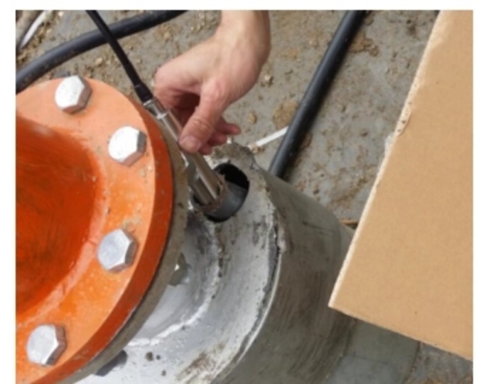
Protect the cable. Strain-relieve at the wellhead so the probe cannot creep down the well, keep the cable clear of the pump column and safety rope, and treat lightning seriously on any rural well: surge protection at the panel is cheaper than a service call to pull 120 m of cable. In corrosive or high-solids groundwater a stainless steel submersible level transmitter or another build from the hydrostatic level sensor line is the correct starting point.
Where the water attacks stainless steel, the SI-302 anti-corrosive submersible level transmitter offers PP or PTFE wetted parts instead.
Choosing a method
The table puts the methods side by side, including whether they still work with the pump running and roughly what they cost. Prices are typical United States street prices for professional equipment.
| Method | Practical depth | Typical accuracy | While pumping | Indicative cost |
|---|---|---|---|---|
| Electric sounder | 30 to 300 m tapes | 0.01 ft class | Only with a clear annulus | From about USD 450 |
| Wetted tape | Under about 30 m | Best available | No | Tape and chalk |
| Air line | To several hundred m | Gauge resolution, about 1 psi = 2.31 ft | Yes, its main advantage | Tube, gauge and fittings |
| Submersible transducer | To 2000 m builds | 0.1 to 0.5 percent of range | Yes, continuously | Sensor plus cable and readout |
| Acoustic well sounder | To a few hundred m | Coarser than a tape | Yes, nothing is lowered | About USD 1,700 and up |
| Dropping an object | Shallow, estimate only | Tens of feet at best | No | No cost, and correspondingly rough |
Representative values; confirm accuracy per datasheet and prices per current quotation.
The last row needs one correction, because the popular version of it is wrong. Timing a dropped stone is free-fall physics, not a linear rule: distance in feet is about 16.1 t², so one second is 16 ft, two seconds is 64 ft, and three seconds is 145 ft, not the roughly 72 ft a linear rule of thumb gives.
Add the time for the sound to travel back up and a three-second measured interval works out near 134 ft. A dropped object also risks jamming beside a pump, and it tells you nothing about the pumping level. Use it only to check an order of magnitude.
Non-contact sensors in wells
Radar and ultrasonic sensors are excellent at looking down at open water, which is why they dominate river and reservoir stations. A producing well is a different geometry, and vendor claims tend to skip past that.
A 150 mm cased well already contains a drop pipe, a power cable and usually a safety rope. Even a narrow 3 degree radar beam spreads to roughly 2.6 m across at 50 m, so in a borehole the beam hits casing, pipe and cable long before it hits water. The returns are strong, close and constant, exactly the kind of false echo that a level instrument locks onto.
The fix is a dedicated guide tube: a straight pipe of 75 mm or larger, running from the wellhead into the water, clear of everything else, with the sensor aimed down it. That is a real installation used in observation wells and large dug wells, and it works.
It is also civil work, which is why the electric tape and the submersible transducer remain the two standard answers in wells while radar owns the open-water case covered in our river water level measurement guide. Ultrasonic adds one more problem in wells: condensation or frost on the transducer face blocks the beam, so the sensor has to sit down inside the casing rather than at the cap.
Drawdown and well health
Static level alone answers half the question. Pair it with the pumping level and the pumped flow rate, and the combined record shows whether the well or the aquifer is changing.
Specific capacity is pumped flow divided by drawdown. A well delivering 20 gpm at 35 ft of drawdown has a specific capacity of 0.57 gpm per foot. That single number, logged the same way every time, separates two failures that look identical from the kitchen tap.
| What the record shows | Most likely cause |
|---|---|
| Static level stable, drawdown rising at the same flow | The well is losing capacity: screen encrustation, biofouling or sand in the gravel pack |
| Static level falling year over year, drawdown steady | The aquifer is declining, from drought or from neighboring pumping |
| Both falling | Both effects present; rehabilitation may buy time but not capacity |
| Static level unchanged, pumping level reaching the intake | The pump is oversized for the well; reduce the rate or add storage |
Compare like with like: same pump, same flow rate, same reference point, and a genuinely rested static reading.
Water in the casing
Once the depth to water is known, the water standing in the casing is straightforward geometry. Casing volume per unit length depends only on the inside diameter.
| Casing inside diameter | Volume per foot | Volume per meter |
|---|---|---|
| 4 in (100 mm) | 0.65 gal | 8.1 L |
| 6 in (150 mm) | 1.47 gal | 18.2 L |
| 8 in (200 mm) | 2.61 gal | 32.4 L |
Volume per length = πr² times length, using the casing inside diameter.
Two cautions apply to that arithmetic. The stored volume is not the yield: a well produces what the aquifer feeds it, and casing storage is only the buffer that covers a short heavy draw. And only the column above the pump intake is usable, so subtract the intake depth before calling it available water. The same distinction between stored volume and delivered volume applies to buried vessels, worked through in our underground tank level measurement guide.
Continuous monitoring and control
A permanently installed transmitter converts spot checks into a record, and a record into protection. The standard chain is a vented submersible transmitter on 4-20 mA into a digital indicator or PLC, with a relay contact set above the pump intake for low-level cutout. Dry-running a submersible pump is the expensive failure this prevents.
Set the trip with hysteresis so the pump does not chatter on a level that hovers near the setpoint, the same deadband logic used for tank pump control in our water storage tank level sensor guide. Where the well feeds a distant tank, HART or Modbus over the existing cable carries level and diagnostics without adding a second pair, and remote sites can log to a cellular gateway on solar power.
Whatever the readout, keep a manual check possible: an access port that admits a sounder tape lets one measurement verify the whole chain.
Application example
Agricultural irrigation, United States. An irrigation operator needed continuous depth to water on two deep wells, each read on a local digital display, and asked whether that display could trigger a relay at a set level. Instranova proposed two submersible level sensors with digital indicators, with the level-triggered relay output to be confirmed against the indicator options. Where an indicator does carry that contact, low-level pump protection sits at the wellhead without a PLC.
FAQ
How do I measure the water level in my well?
Lower an electric sounder tape down the well until the probe signals at the water surface and read the depth at the top of casing. Rest the pump at least two hours first if you want a static level. For a permanent reading, install a vented submersible pressure transmitter and subtract its measured water column from the cable length.
What is a good static water level for a well?
There is no universal number; it depends entirely on local geology, and a good static level in one valley is a dry well in the next. What matters is the trend at your own well, plus enough submergence over the pump intake at the pumping level. Compare each reading against your own baseline, taken the same way at the same reference point.
How do I know if my well is running low on water?
The reliable early signs are in the record, not the tap: a static level falling year over year, or drawdown increasing at the same pumped flow rate. Air spitting from faucets, sediment and a pump that short-cycles usually mean the pumping level has already reached the intake. Measure both levels before deciding whether the problem is the aquifer or the well.
How to tell how much water is left in a well?
Measure the depth to water, subtract it from the depth of the pump intake, and multiply that column by the casing volume per unit length: about 1.47 gallons per foot in a 6 inch casing. That gives stored water only. Sustained supply comes from the aquifer’s recharge rate, which is measured by a pumping test, not by a level reading.
Request a quote
Tell us the application and we configure one system, not a shelf part. Send the well depth and casing size, the expected range of water levels, the pump intake depth, which output or telemetry the site needs, and whether the water is corrosive or carries sand. Reach our application engineers or use the form below.
Written and technically reviewed by Wu Peng and the Instranova engineering team.