By Wu Peng, Senior Process Instrumentation Engineer · Last reviewed August 14, 2026
The HART communication protocol (Highway Addressable Remote Transducer) puts a digital conversation on top of an ordinary 4-20 mA current loop. A small alternating current, 1 mA peak to peak, rides on the DC measurement signal at 1200 bits per second, so one pair of wires carries both the analog reading the control system has always used and the digital data a technician needs.
The concept is simple. What trips people up is the wiring condition underneath it: the loop needs at least 230 ohms of resistance before anyone can hear the digital signal, and that resistance costs supply voltage. This guide covers the signal, the resistance and voltage budget with the arithmetic worked out, the four device variables, what changed across HART 5, 6 and 7, and where the protocol runs out of room.
Contents
- What HART adds
- Loop resistance and voltage
- The four device variables
- HART revisions
- Multidrop and burst mode
- Limits of HART
- Specifying a HART device
- FAQ
What HART adds
A plain 4-20 mA transmitter sends one number. HART keeps that number and adds a digital channel for everything else: the tag, the range, the units, the sensor temperature, the diagnostic status, and the trim commands a technician sends back down the same wires.
The digital part uses frequency shift keying to the Bell 202 standard. A 1200 Hz tone is a logical 1 and a 2200 Hz tone is a logical 0, sent at 1200 bits per second, which puts each bit at 833 microseconds. Those tones are carried as an alternating current of 1 mA peak to peak, so ±0.5 mA either side of whatever DC current the transmitter is putting out.
That amplitude sounds like it should corrupt the measurement, and this is the point most explanations get wrong. The analog reading survives not because the two tones balance each other, but because each tone is a sine wave symmetric about zero: it has no DC component at all. The control system’s input filter, which is looking at frequencies below about 20 Hz, sees the average, and the average of the superimposed signal is zero. The digital traffic and the analog reading share a wire without either one moving the other.
Loop resistance and voltage
HART modems do not read current; they read the voltage that current develops across a resistance. No resistance, no voltage, no communication. This is why a bench test with a transmitter, a power supply and a milliammeter fails to talk while the same transmitter works fine once it is wired into the plant.
The working window for total loop resistance is 230 to 1100 ohms, and the two ends exist for completely different reasons.
| Bound | Why it is there |
|---|---|
| 230 ohm minimum | Below this the 1 mA signal develops too little voltage for the listening modem to decode reliably. At the common 250 ohm value the signal is 250 mV peak to peak, which is comfortable. |
| 1100 ohm maximum | Nothing to do with HART. It is the DC voltage budget: resistance times 20 mA is voltage the transmitter no longer has, and a 2-wire transmitter needs roughly 10.5 V at its terminals to run at all. |
Published minimums vary between 230 and 250 ohms depending on whose document you read. 230 is the physical-layer floor; 250 is the value the industry actually installs.
Put numbers on the upper bound and it stops being abstract. A device maker’s own load curve expresses the limit as a straight line:
Rmax = (E − 10.5) / 0.0244
where E is the supply voltage. At E = 24 V that gives 553 ohm. At E = 16.6 V it gives 250 ohm, which is the point where the standard sampling resistor only just fits.
The 0.0244 in the denominator is a current, about 24.4 mA. Load curves size the loop for the highest current the device can drive, which sits above the 20 mA span end so that an over-range or alarm output still has voltage to work with. The rounder sums below use 20 mA, so they are the best case rather than the worst.
Read that second result again, because it is the practical takeaway: below roughly 16.6 V of supply, a 250 ohm resistor leaves the transmitter starved. And the 1100 ohm figure at the top of the range needs 22 V of drop across the resistor alone, so it only exists on loops running a supply above about 32.5 V.
The everyday budget on a 24 V loop works out like this. Start with 24 V, hand 10.5 V to the transmitter, and 13.5 V is left. The 250 ohm resistor takes 5.0 V of that at full scale. The remaining 8.5 V has to cover cable resistance, any barrier, and margin for a sagging supply.
That last item catches people in hazardous areas. An intrinsic safety barrier has resistance of its own, and it counts against the same budget as the sampling resistor and the wire. If a loop is marginal, the barrier is usually the part nobody added up. The rest of the loop arithmetic, including how supply voltage sets the maximum load in a plain analog loop, is in the 4-20 mA current loop guide.
The four device variables
A HART device publishes up to four dynamic variables, and their names appear on every configuration screen: PV, SV, TV and QV, for primary, secondary, tertiary and quaternary.
| Variable | What it usually carries |
|---|---|
| PV (primary) | The measurement the 4-20 mA current represents. This is the only one the analog side can carry. |
| SV (secondary) | On a pressure transmitter, typically the sensor or electronics temperature. On a mass flow meter, often density or temperature. |
| TV (tertiary) | A third measured or derived value, where the device supports one. |
| QV (quaternary) | A fourth value, most common on multivariable transmitters and flow computers. |
The mapping matters when you order. Which physical measurement lands on PV decides what the analog output does, and a multivariable transmitter reporting all four variables over HART still drives exactly one 4-20 mA signal. If the control system needs the extra variables as analog inputs, they have to be split out by a device that converts HART variables back to current, which is a different piece of equipment from a plain 4-20 mA signal splitter.
HART revisions
Three revisions are in service. A device built to one revision talks to a host built for another, but the newer features simply do not appear.
| Revision | Multidrop addresses | What it brought |
|---|---|---|
| HART 5 | 0 to 15 | The baseline still found across installed plant: FSK physical layer, 8-character tag, burst mode, four dynamic variables. |
| HART 6 | 0 to 63 | Expanded address range and command set, extended manufacturer identification, and the optional C8PSK physical layer at 9600 bps. |
| HART 7 | 0 to 63 | 32-character long tags, configurable burst with event notification, time stamps, device locate, and WirelessHART. |
Address 0 is the point-to-point address, where the current still swings 4 to 20 mA. Addresses 1 upward are multidrop, so the usable device count is 15 on HART 5 and 63 on HART 6 or 7, not 16 and 64.
For most buyers the revision only becomes a live question in two places: whether the plant’s asset management software has a device description file for the revision your instrument reports, and whether you need long tags. Everything else is comfortably backward compatible.
Multidrop and burst mode
These two get confused constantly, including in published explanations. They are unrelated: multidrop is about wiring and addressing, burst is about who speaks first.
Multidrop parks several transmitters on one pair of wires. Each takes a polling address above zero and, in return, gives up the analog output entirely: its current is parked at 4 mA and no longer represents anything. All readings come back digitally. That is the trade, and it is why multidrop suits tank farms and monitoring points rather than anything a controller has to close a loop around.
Burst mode is a messaging change on any loop, multidrop or not. Instead of waiting to be polled, the device repeats its reply continuously. Polled HART manages roughly two to three updates per second because a full request and reply takes about half a second; burst lifts that somewhat by removing the request.
On HART 7 the burst period and trigger are configurable, so a single fixed number is misleading. What is worth knowing is that if you burst three variables, each individual variable arrives less often than the headline rate suggests.
Application example
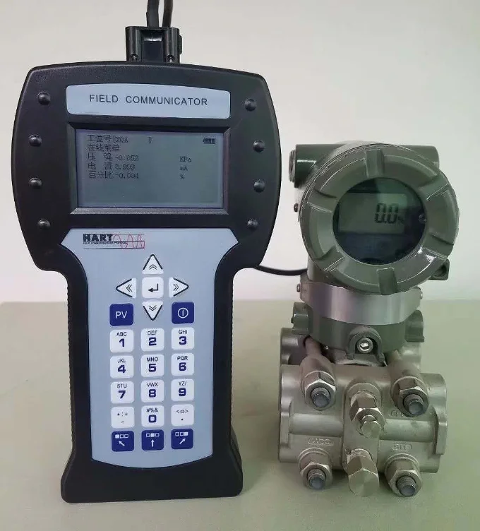
Instrument distributor, replacement differential pressure transmitters. A distributor asked for two DP transmitters to replace an existing unit from another brand, spelled out to the digit: 0 to 4 bar, −20 to 80 °C, 4-20 mA with HART, local display, IP66, non-hazardous area, 0.075 percent accuracy, M20 x 1.5 entry. We proposed a matching build against that list. A like-for-like HART swap is two checks, not one: the replacement has to speak HART, and the loop it lands in still has to hold 230 ohms.
Limits of HART
HART works by riding existing wiring, and every limitation follows from that.
It is slow. Two to three updates per second is fine for diagnostics, configuration and secondary variables, and useless as a control path. Anything that needs faster closed-loop data stays on the analog signal, which is exactly the division of labor the protocol was designed around.
It is master and slave, not peer to peer. A field device answers when asked; it does not start conversations, and burst mode is a scheduled reply rather than an exception. It also carries a modest payload, so it moves parameters and status rather than bulk data.
And it depends on that loop resistance. A HART device wired into a loop with too little resistance still measures correctly and still outputs 4 to 20 mA. It just goes deaf, and the symptom in the field is a handheld that will not connect while the reading on the screen looks perfectly healthy. If a loop is behaving strangely in other ways, the pressure transmitter troubleshooting guide walks the usual suspects.
Specifying a HART device
Five lines cover most of what a supplier needs to configure a HART instrument correctly rather than ship a default.
| What to state | Why it changes the build |
|---|---|
| HART revision required | Some transmitters are ordered as revision 5 or 7 and set at the factory. Match whatever your asset management software has device description files for. |
| Supply voltage and loop resistance | Decides whether the loop can carry the sampling resistor at all. State the barrier if there is one. |
| Point-to-point or multidrop | Multidrop fixes the current at 4 mA and needs a polling address assigned per device. |
| Variable mapping and units | Which measurement is PV, and what SV should report. This is set before shipment when you say so. |
| Tag and range | Long tags need revision 7. Range and damping are configured digitally, so send them with the order. |
On the instrument side, HART is available across the range rather than being a product of its own: our HART pressure transmitter page covers the pressure build with its specifications, and the same signaling appears on the temperature transmitter and across the pressure transmitter range. Configuration over HART also changes how calibration is done, since trimming the sensor and trimming the analog output become separate operations, covered in the pressure transmitter calibration guide.
Whether to specify HART, Modbus or a plain loop on a given instrument is decided in HART vs Modbus vs 4-20 mA.
FAQ
What is the difference between HART and 4/20mA?
4-20 mA is the analog current signal that carries one measurement. HART is a digital protocol layered on top of that same current loop, adding tag, range, diagnostics and configuration without disturbing the analog value. Every HART device is also a 4-20 mA device; not every 4-20 mA device speaks HART.
Why do you need a 250 ohm resistor in HART protocol?
A HART modem detects voltage, not current. The 1 mA peak-to-peak digital signal needs resistance to develop a readable voltage, and 250 ohms gives 250 mV peak to peak. The physical-layer floor is 230 ohms, and 250 is the value normally installed. Many control system input cards already contain it.
What are the disadvantages of HART?
Speed above all: roughly two to three updates per second, which suits diagnostics and configuration but not control. It is also master and slave rather than peer to peer, carries a small payload, needs at least 230 ohms in the loop to communicate, and gives up the analog output on every device once you go multidrop.
What are the key differences between Modbus and HART?
HART is a hybrid: digital data superimposed on an analog 4-20 mA loop, so one instrument keeps working with analog input cards. Modbus is fully digital, usually over RS-485 or TCP, with no analog signal and no per-device current loop. Modbus moves more data and more registers; HART keeps the installed analog wiring and adds diagnostics to it.
Request a quote
Tell us the measurement, the loop supply voltage, whether there is a barrier, and which HART revision your asset management software expects. We will confirm the loop can carry the resistance HART needs and configure tag, range and variable mapping before the instrument ships. Reach our application engineers or use the form below.
Written and technically reviewed by Wu Peng and the Instranova engineering team.