By Wu Peng, Senior Process Instrumentation Engineer · Last reviewed August 7, 2026
Home › Tools › Linear to Square Root Calculator
This calculator converts a linear 4-20 mA differential pressure signal to its square root extraction equivalent and back, in mA and in percent, with an optional low-flow cutoff. A third mode generates the three currents that tell you whether your loop extracts the square root once, twice, or not at all. The core relationship: mA out = 4 + 16 × √((mA in − 4) / 16).
The conversion exists because an orifice, venturi, nozzle or averaging pitot tube produces a differential pressure that rises with the square of flow. To read in flow, the DP signal must be square-rooted exactly once. The physics is in our guide to the flow rate and pressure relationship.
Calculator
Linear and square root 4-20 mA converter
Results update as you type. The tool assumes a healthy 4-20 mA signal and one square root extraction per loop. Percentages are of span; the flow rate line simply scales your 100% flow value.
How the conversion works
A DP flow element obeys Q proportional to √ΔP. A transmitter spanned in pressure sends a signal linear in DP; a transmitter with square root extraction turned on sends a signal linear in flow. The two travel on identical 4-20 mA wiring, which is where the confusion starts. In signal terms, both directions are one line each:
Square root mA = 4 + 16 × √((linear mA − 4) / 16)
Linear mA = 4 + (square root mA − 4)2 / 16
In percent it is shorter still: flow % = 10 × √(DP %). The classic check figures: 25 percent DP is 50 percent flow, and 50 percent DP is 70.71 percent flow.
So a 12 mA linear signal, which is 50 percent DP, converts to 15.314 mA on a square root scale. An 8 mA linear signal converts to exactly 12 mA. The calculator reproduces every one of these.
Conversion table
| Linear signal | DP, % of span | Flow, % of span | Square root signal |
|---|---|---|---|
| 4 mA | 0 | 0 | 4.000 mA |
| 5 mA | 6.25 | 25.00 | 8.000 mA |
| 6 mA | 12.5 | 35.36 | 9.657 mA |
| 8 mA | 25 | 50.00 | 12.000 mA |
| 10 mA | 37.5 | 61.24 | 13.798 mA |
| 12 mA | 50 | 70.71 | 15.314 mA |
| 14 mA | 62.5 | 79.06 | 16.649 mA |
| 16 mA | 75 | 86.60 | 17.856 mA |
| 18 mA | 87.5 | 93.54 | 18.967 mA |
| 20 mA | 100 | 100 | 20.000 mA |
Values are exact for an ideal signal; percentages are of the respective spans.
Extract once, not twice
The square root belongs in exactly one place per loop: the transmitter or the control system, never both and never neither. Configured in both, the loop applies a fourth root to the DP; configured in neither, the display reads DP while everyone believes it reads flow. The failure has clean signatures. Apply 50 percent DP on the bench and read the loop display path:
- Reads like 12.000 mA (50% of scale): no extraction anywhere
- Reads like 15.314 mA (70.7%): one extraction, correct
- Reads like 17.454 mA (84.1%): extraction on both ends
The quick field version needs no bench: at 25 percent DP, a linear transmitter puts 8 mA on the wire and a square-rooting one puts 12 mA. The extraction-check mode above prints all three signatures for any test point.
Where should the single extraction live? Both answers are defended in print. In the transmitter, low-flow noise on the mA wire is not amplified by a controller-side square root; in the DCS, the arithmetic is easier to audit. Either works; what prevents the double-extraction fault is a plant-wide rule that says which one, written down.
The low end is the risky part. Because flow % = 10 × √(DP %), the curve is steepest near zero. At 10 percent flow, only 1 percent of DP span is behind the reading. A DP error of 0.1 percent of span moves the flow reading by about 0.5 percent of span there, a five-fold amplification.
That amplification is why DP flow turndown is practically 3:1 to 10:1. It is also why transmitters apply a low-flow cutoff, typically at 5 to 10 percent of flow, forcing the output to 4 mA below it. With a 10 percent flow cutoff, everything below 5.6 mA on the square root scale is a forced zero, not a measurement.
Worked example
An orifice run is sized so that 25 kPa of differential pressure corresponds to 100 m³/h. The DP transmitter is left linear, and the DCS does the extraction. The loop current sits at 12.00 mA:
- DP = (12 − 4) / 16 × 25 kPa = 12.5 kPa, 50% of DP span
- Flow = √0.5 × 100 = 70.7 m³/h, 70.71% of flow span
- Had the transmitter been doing the extraction instead, the same flow would put 15.314 mA on the wire
Set the calculator to linear-to-square-root, 12 mA, flow at 100 percent = 100 m³/h, and it returns each of these lines.
Application example
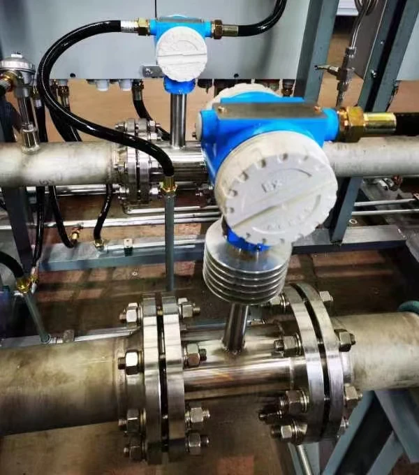
Power plant, South Africa. A steam line called for an averaging pitot tube on DN200 pipe at 35 to 55 t/h, 500 °C and 67 bar, with a DP transmitter and flow totalizer. We proposed the element and transmitter as a matched pair; in a chain like this the extraction belongs in one recorded place, and running it in the transmitter lets the totalizer integrate a signal already linear in flow. With three instruments on one loop, writing down which box owns the square root keeps the totalized figure correct.
Calibration check points
A square-root-configured transmitter is checked against the curve, not against straight percentages. The bench points that correspond to round output currents:
| Flow point | Output | DP to apply, % of span | On a 0-25 kPa span |
|---|---|---|---|
| 10% | 5.600 mA | 1.00 | 0.25 kPa |
| 25% | 8.000 mA | 6.25 | 1.56 kPa |
| 50% | 12.000 mA | 25.00 | 6.25 kPa |
| 75% | 16.000 mA | 56.25 | 14.06 kPa |
| 100% | 20.000 mA | 100.00 | 25 kPa |
The lowest trim point is taken at 10 percent flow rather than zero, because the curve is near-vertical at the origin and a zero-point trim there is unstable.
The full five-point procedure, tolerance math and trim taxonomy are in our pressure transmitter calibration guide, published alongside this tool.
Related guides and tools
The flow rate and pressure relationship guide derives why Q goes with the square root of DP and works the element sizing math. To go from a DP reading straight to a flow rate in engineering units, the flow rate from pressure calculator handles orifice, rescale and valve Cv cases. On the product side, an orifice plate or another element from our differential pressure flow meter series pairs with a differential pressure transmitter. The transmitter can be configured either way this page describes.
The equation that produces the DP signal in the first place, and the worked examples for turning it into a flow value, are in the differential pressure flow calculation guide.
FAQ
Why is flow measured in square root?
Because a DP flow element produces a differential pressure proportional to the square of flow. Reading flow from that signal means taking the square root exactly once: 25 percent of DP span corresponds to 50 percent of flow span. The extraction runs in the transmitter or in the control system.
Which of the following flow measurement devices requires square root extraction?
The differential pressure elements: orifice plates, venturi tubes, flow nozzles, averaging pitot tubes and wedge meters. Magnetic, turbine, ultrasonic, Coriolis and positive displacement meters are already linear in flow and must not be square-rooted.
How to square root a flow transmitter?
Set the transfer function in the transmitter configuration from linear to square root, using the local display or a HART communicator. Confirm the control system input is set to linear so the extraction happens only once. Then verify at 25 percent DP: the output should read 12 mA, not 8 mA.
What is the square root extraction method?
It is the conversion of a linear differential pressure signal into a signal linear in flow, using flow % = 10 × √(DP %). In current terms, square root mA = 4 + 16 × √((linear mA − 4) / 16), so 12 mA linear becomes 15.314 mA.
Request a quote
Tell us the application and we configure one system, not a shelf part. Pipe size, media, flow range and where you want the extraction to live are enough for a DP flow proposal. Reach our application engineers or use the form below.
Written and technically reviewed by Wu Peng and the Instranova engineering team.