By Wu Peng, Senior Process Instrumentation Engineer · Last reviewed August 7, 2026
To calibrate a pressure transmitter, apply known pressures at 0, 25, 50, 75 and 100 percent of the calibrated span, record the output at each point, and compare every reading against a written tolerance. The expected output is mA = 4 + 16 × (P − LRV) / (URV − LRV). If all points fall inside the tolerance, document the results and stop. Only when a point fails do you adjust anything.
The published advice around that simple procedure is a mess. Top-ranking guides recommend calibration intervals anywhere from six months to six years. Reference-accuracy advice runs 3:1, 4:1, or 4-10:1, without telling you which applies to your service.
This guide gives the working numbers. You get a five-point tolerance calculation in mA, a filled-in as-found and as-left record, the four kinds of adjustment, and a defensible way to set the interval.
Contents
- Why transmitters drift
- Tolerance before tools
- Reference equipment ratios
- Bench procedure
- Trim or re-range
- DP transmitter calibration
- Absolute and vacuum units
- Loop test limits
- Calibration intervals
- Records and certificates
- FAQ
Why transmitters drift
A pressure transmitter changes slowly. Piezoresistive bridges age, diaphragms take a set after overpressure events, process deposits add a standing load, and the electronics shift with temperature cycles. Manufacturers publish long-term stability figures such as 0.1 percent of range per 10 years, and some guarantee 5-year or even 10-year stability on premium models. Those figures are statistical limits for a population of instruments, not a promise about the one bolted to your line.
Calibration is how you replace that assumption with a measurement. It also catches the failures stability specs never cover. A plugged impulse line, a diaphragm coated in product, a re-ranged transmitter nobody documented: all of them show up in an as-found check. Our pressure transmitter series ships with a factory calibration; everything below is about proving the instrument still holds it in service.
Tolerance before tools
Decide what “pass” means before you connect anything. The acceptance limit goes by maximum permissible error (MPE), and the most common mistake is copying the manufacturer’s reference accuracy straight into the calibration sheet. A cell specified at ±0.075 percent of span will fail such a check constantly once installation, temperature and drift are on top of it.
Set the MPE from what the loop needs, typically 2 to 4 times looser than reference accuracy. The distinction between span-based and reading-based error statements matters here; see full scale vs of-reading accuracy.
With the MPE fixed, convert it into a current band. Errors are stated as percent of span, taken against the ideal output:
Error (% of span) = (mA found − mA expected) / 16 × 100
Worked setup for the rest of this guide: a transmitter calibrated 0 to 600 kPa gauge, MPE of ±0.2 percent of span. The span is 16 mA, so the acceptance band is ±0.032 mA, which is ±1.2 kPa of pressure. The expected outputs:
| Point | Applied | Expected | Acceptance band |
|---|---|---|---|
| 0% | 0 kPa | 4.000 | 3.968-4.032 |
| 25% | 150 kPa | 8.000 | 7.968-8.032 |
| 50% | 300 kPa | 12.000 | 11.968-12.032 |
| 75% | 450 kPa | 16.000 | 15.968-16.032 |
| 100% | 600 kPa | 20.000 | 19.968-20.032 |
Outputs and acceptance bands in mA; band = expected output ±0.032 mA for an MPE of 0.2% of a 16 mA span. Terminology for calibration, verification and adjustment follows our calibration vs verification guide.
Reference equipment ratios
The reference standard has to be meaningfully better than the transmitter. The classic target is a 4:1 test accuracy ratio, carried over from ANSI/NCSL Z540 practice. Some manufacturers accept 3:1 as a pragmatic floor.
For the 600 kPa example with an MPE of ±0.2 percent of span, 4:1 means the pressure reference must be accurate to ±0.05 percent, or ±0.3 kPa at full scale. One well-known calibration page manages to recommend both “4-10 times” and “at least three times” in the same article. Treat any single ratio you read as a policy choice, not physics.
Modern transmitters make the ratio hard to keep. Against a 0.04 percent cell, 4:1 demands a 0.01 percent reference, which calls for a deadweight tester. When you cannot reach the ratio, shrink the acceptance band with a guard band instead of pretending; the decision-rule arithmetic is worked through in the verification guide.
Typical bench equipment: a pressure hand pump or screw-press comparison pump sized comfortably above the span, plus a reference gauge or pressure module with a current calibration certificate. Add a milliammeter or loop calibrator good to 0.01 mA or better, and a HART communicator for smart units. A 24 VDC supply with a series connection for the mA reading completes the loop.
Application example
Pressure calibration, Middle East. A customer asked for a hydraulic comparison pump rated to 700 bar, naming a model we do not carry. We proposed an equivalent 700 bar screw-press unit: transmitter and reference gauge mount on twin test ports, so both see identical pressure at each point. The requirement worth copying is the headroom: the pump must generate and hold the full upper range value of the highest-range instrument on the bench.
Bench procedure
With the transmitter isolated and removed, or valved off on a bench stand, the sequence is short. Smart transmitter menus differ, but the measurement logic does not.
1. Mount and exercise. Set the transmitter in its service orientation, then stroke the sensor two or three times to near its upper range limit, holding for about 30 seconds each time. A cell that has sat at one pressure for months reads differently on the first stroke than the third, so exercise first and you record the instrument, not its history.
2. Connect. Pressure source and reference to the process connection, milliammeter in series with the loop. Give the electronics a few minutes to warm up.
3. Record as-found. Apply each of the five points going up, then the same points coming down, waiting up to 30 seconds for stabilization at each; the downscale pass exposes hysteresis that a rising-only check hides. Write every reading down before touching any adjustment.
4. Decide. Inside the MPE at every point: the as-found data is the record, the transmitter goes back to work, and no trim is performed. Chasing a passing instrument toward zero error adds risk for nothing.
5. Trim and record as-left. Out of tolerance at any point: perform the appropriate trim (next section), then repeat the full five-point run as the as-left record.
Here is the worked record for the 600 kPa transmitter, showing the span drift pattern you will see most often, with error growing in proportion to reading:
| Point | As-found | Error | Verdict | As-left | Error |
|---|---|---|---|---|---|
| 0% | 4.010 | +0.06% | Pass | 4.002 | +0.01% |
| 25% | 8.022 | +0.14% | Pass | 8.003 | +0.02% |
| 50% | 12.034 | +0.21% | Fail | 12.004 | +0.03% |
| 75% | 16.046 | +0.29% | Fail | 16.006 | +0.04% |
| 100% | 20.058 | +0.36% | Fail | 20.008 | +0.05% |
Worked example against the ±0.2% of span MPE, rising points shown; as-found and as-left values in mA, errors in percent of the 16 mA span. Illustrative record, not a customer measurement. An upper sensor trim corrected the span drift.
Trim or re-range
A smart transmitter has three places its signal can be corrected and one place it can only be reconfigured. Mixing them up is the most common way a good cell gets made worse.
| Adjustment | What it corrects | When to use it |
|---|---|---|
| Zero trim | Digital sensor reading, offset only, at true zero pressure | After installation, to remove the mounting-orientation shift; a gauge unit vented to atmosphere |
| Sensor trim | Digital sensor reading at a lower and an upper applied pressure | As-found failure traced to the measurement itself, with a reference source connected |
| Output trim | The D/A stage, so 4.000 and 20.000 mA leave the terminals exactly | Sensor reads right but the measured current disagrees with a reference milliammeter |
| Re-range | Nothing. Changes LRV and URV in configuration | The span assignment was wrong for the service; it is not calibration and corrects no error |
Two rules keep this table safe. First, trim only on a documented failure. A new transmitter carries a factory characterization built from more test points than any field bench applies. Trimming it against a lesser reference degrades it.
Second, zero trim in place is legitimate and cheap. Mounting orientation alone can move zero by around a millibar on sub-bar ranges; on a 100 mbar span that is 1 percent of span. Our installation guide covers that shift and why zeroing happens after mounting, in the final orientation. On HART transmitters all four operations live in different communicator menus; the menu names differ by vendor, the four functions do not.
DP transmitter calibration
A differential pressure transmitter adds the manifold to the job. Before applying test pressure, block both process sides and open the equalizer so the cell sees zero differential. Then vent the low side and apply the test pressures to the high side. The valve orders for taking a DP transmitter out of service and returning it, without over-ranging one side of the cell, are in the installation guide’s manifold section.
Two extra checks are worth the minutes. An in-place zero, with the low side blocked and the equalizer open, confirms zero under working static pressure without demounting anything. On 5-valve manifolds, applying equal static pressure to both sides checks the static-pressure effect against its spec.
One trap is specific to DP flow service. A transmitter configured for square root extraction does not sit at 8 mA when 25 percent differential is applied; it sits at 12 mA, because output tracks flow, not pressure. Calibrate it against the square root curve, or the record is meaningless. The check points and both conversion formulas are in our linear to square root calculator.
Absolute and vacuum units
An absolute pressure transmitter cannot be zeroed by venting. Vented to atmosphere at sea level, a 0 to 200 kPa absolute unit should read about 101.3 kPa, which is 12.10 mA. Weather moves that reference by roughly ±3 kPa, or ±0.24 mA, 1.5 percent of span.
Anyone who “zeros” an absolute unit against room air has just written the day’s weather into the instrument. A proper zero point needs a vacuum pump pulling well below the resolution you care about. The practical alternative is a two-point check: at atmospheric pressure read from a calibrated barometer, and at a pumped upper point. Vacuum and compound ranges follow the same rule: the reference is a measured absolute pressure, never an assumed one.
Loop test limits
A fixed-current loop test, where the communicator forces the output to 4, 12 and 20 mA, proves the wiring, the power supply and the input card. It says nothing about the sensor, because the forced current bypasses the measurement entirely. The reverse also holds: a bench calibration does not prove the loop. A complete check is both, and the commissioning sequence in the 4-20 mA loop guide covers the loop half, including what the receiving card should show at each forced current.
Calibration intervals
The six-months-to-six-years spread in published advice is not a contradiction; it is different services being quoted without their context. Set the starting interval by consequence, and adjust it from the as-found record over time:
| Service | Starting interval |
|---|---|
| Custody transfer, fiscal metering | Whatever the contract says, commonly 6 to 12 months |
| Safety instrumented functions | At the proof-test interval defined in the safety requirement specification |
| Process control loops | 12 to 24 months to build a history |
| Stable indoor monitoring | Multi-year; one manufacturer guidance for controlled environments runs 4 to 6 years |
| Remote diaphragm seals, frequent overpressure | Halve the interval the table above would give |
Starting points, not regulations; site quality systems and local law override.
The history rule is what makes the number defensible. Two consecutive as-found records inside the MPE justify extending the interval. One out-of-tolerance result halves it, and triggers an impact review of every measurement made since the last good check.
That review is the expensive part, which is why an MPE set deliberately looser than reference accuracy saves money twice. Flow instruments carry their own logic on this; see flow meter calibration.
Records and certificates
A calibration that is not documented did not happen, as far as an auditor is concerned. The record needs the instrument tag and serial, the calibrated range and MPE, and the reference standards used with their certificate numbers and traceability chain.
It also needs ambient conditions, every as-found and as-left point with pass or fail against the MPE, any adjustment performed, the technician, and the date. ISO 9001 clause 7.1.5 requires traceable references and records for any measurement that proves product conformity; accredited ISO/IEC 17025 certificates are the stricter tier for references and disputes.
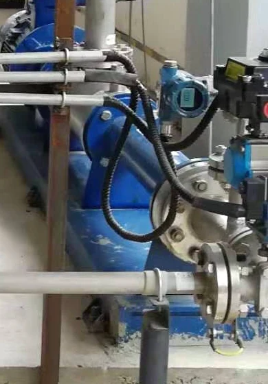
Instranova transmitters are bench-calibrated before dispatch, and a calibration certificate with as-left data can be supplied when the order calls for it. If your quality system needs a specific format, send it with the inquiry.
If the as-found error turns out to be wiring or supply voltage rather than drift, work through our pressure transmitter troubleshooting guide before trimming anything.
A zero that keeps drifting on a corrosive line can be the diaphragm thinning rather than the electronics; the wetted parts and materials guide covers how to read that pattern.
Mechanical dial gauges follow a bench routine of their own, with class based acceptance bands; it is covered in the pressure gauge calibration guide.
FAQ
Can you calibrate a pressure transmitter?
Yes. You need a traceable pressure reference, a way to generate stable pressure, and a milliammeter for the output. Record five points as found, compare against your tolerance, and trim only if a point fails. Smart transmitters are adjusted through sensor and output trims; analog units use zero and span screws.
How often should a pressure transmitter be calibrated?
There is no single correct interval. Start from the service: contract terms for custody transfer, the proof-test interval for safety functions, 12 to 24 months for general process loops, and multi-year for stable indoor monitoring. Then let as-found history adjust it: repeated in-tolerance results extend the interval, one failure halves it.
How do you calibrate 4-20mA?
Check the current at 0, 25, 50, 75 and 100 percent of span against mA = 4 + 16 × (P − LRV) / (URV − LRV), using a reference milliammeter. If the sensor reads correctly but the current is off, perform an output trim so the D/A stage puts exactly 4.000 and 20.000 mA on the wire. A forced-current loop test then proves the rest of the loop.
What is the formula for calibration of a pressure transmitter?
Expected output in mA = 4 + 16 × (P − LRV) / (URV − LRV), where P is the applied pressure and LRV and URV are the range values. Error as percent of span = (found mA − expected mA) / 16 × 100. For a 0 to 600 kPa range at 300 kPa: 4 + 16 × 0.5 = 12 mA.
Request a quote
Tell us the application and we configure one unit, not a shelf part. Range, media, process connection and the certificate your quality system needs are enough to start. Reach our application engineers or use the form below.
Written and technically reviewed by Wu Peng and the Instranova engineering team.