By Wu Peng, Senior Process Instrumentation Engineer · Last reviewed August 6, 2026
Installing a pressure transmitter comes down to four decisions: where to tap the pipe, where the transmitter sits relative to that tap, how the impulse line runs between the two, and how the loop is wired. The core rules are short.
Gas taps go on top of the pipe with the transmitter above. Liquid and steam taps go on the side with the transmitter below. Every impulse line slopes at least 8 cm per meter (about 1 inch per foot). And the zero gets checked after mounting, never before.
Get one of those wrong and the instrument stops reading the process. It reads a gas pocket in the impulse line, a forgotten condensate column, or 60 Hz noise from the cable tray instead. This guide walks the full sequence for gauge, absolute, and differential transmitters: tap location, mounting, impulse line rules with the actual numbers, the steam hookup, manifold valve order, loop wiring, and the zero work that closes the job out.
Contents
- Choosing the tap
- Tap orientation by service
- Mounting and support
- Impulse line rules
- Steam service hookup
- Manifold valve sequence
- Wiring the loop
- Zero after mounting
- Commissioning checklist
- FAQ
Choosing the tap
Pick the tap point before you think about brackets or tubing. A pressure tap only reports true static pressure when the flow past it is settled, so keep it on a straight run, away from elbows, control valves, and reducers. Swirl right after a fitting shows up as a noisy reading, and no damping setting truly fixes it; damping only hides it from the display.
Drill the tap flush with the inside wall and deburr it. A stub that protrudes into the flow picks up velocity head and reads high or low depending on its angle. Keep the tap away from pump discharge pulsation and from spots where condensate slugs slam into the pipe. If the only available point sits near a reciprocating pump, plan for a snubber and expect to service it.
Two more rules cost nothing during construction and save a shutdown later. First, never tap the bottom of the pipe: sediment finds a 6 o’clock tap within weeks and plugs it. Second, fit an isolation valve (the root valve) at every tap. Without one, the next zero check means depressurizing the whole line.
Tap orientation by service
On a horizontal pipe, the clock position of the tap decides which phase enters the impulse line, and the elevation of the transmitter decides whether that phase stays there or escapes back to the process. The convention below follows API RP 551 practice.
| Service | Tap position on the pipe | Transmitter position |
|---|---|---|
| Liquid | Side, from the centerline to 45° below | Below the tap, so bubbles rise back to the process |
| Gas | Top, within 45° of vertical | Above the tap, so droplets drain back to the line |
| Steam | Side, from the centerline to 45° above | Below the tap, behind a water-filled leg |
Per API RP 551 practice. Never tap the bottom of the pipe on any service; confirm angles against your site piping specification.
The logic is the same in all three rows: keep the wrong phase out of the impulse line. A liquid line must stay liquid full, a gas line must stay dry, and a steam line must present condensate, not steam, to the sensor. The hookup drawing for each case looks like this:
On a vertical pipe there is no clock position, but the elevation rules still hold: the transmitter goes below the tap for liquid and steam, above it for gas.
Mounting and support
Where temperature and vibration allow, thread the transmitter directly onto the root valve. Direct mounting removes the impulse line entirely, which removes the plugging, freezing, and slope questions with it. Where the process is too hot, too shaky, or too far from a walkway, mount the transmitter on a 2-inch pipe stand with the manufacturer bracket and run tubing between the two.
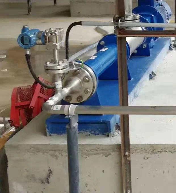
Keep the electronics inside their ambient rating, typically −40 to +85 °C for the housing even when the process runs far hotter. The process heat is handled upstream of the electronics: by the standoff, by an uninsulated run of impulse line, or by a diaphragm seal with capillary when the medium also crystallizes or corrodes. Point the cable entry down, or loop the cable below the gland so water drips off the loop instead of tracking into the housing, and plug the unused entry.
Seal the process connection by its own rules. Tapered NPT threads seal on the thread itself and need PTFE tape or paste, tightened wrench tight, typically two to three turns past finger tight.
Parallel G threads seal on a gasket at the shoulder and carry a torque limit that depends on the seal type: single-digit N·m for O-ring seals, 25 to 50 N·m for metal profile seals. Take the number from the datasheet rather than from feel, and always wrench on the hex flats, never on the housing. Over-tightening does not just risk the threads; it strains the body enough to shift the zero.
Impulse line rules
An impulse line is the small-bore tube or pipe that carries process pressure from the tap to the transmitter. It is passive, cheap, and responsible for more bad readings than the sensor it feeds. Four numbers keep it reliable:
| Parameter | Rule |
|---|---|
| Slope | At least 8 cm per meter (1 in/ft), continuously, with no flat spots |
| Direction | Liquid and steam rise toward the tap; gas falls toward the tap |
| Bore | 10 mm (3/8 in) minimum; 12 mm (1/2 in) for steam and longer runs |
| Length | As short as practical; treat 15 m as a ceiling, not a target |
Slope figure per Rosemount 3051 reference manual practice; confirm bore and routing against your hookup drawing.
The slope rule exists so the line cleans itself. A liquid-filled line with a high point traps a bubble that makes the reading spongy and slow; a gas line with a low point collects a slug of condensate that reads as extra pressure. If the routing forces a high point in a liquid line, put a vent fitting there; if it forces a low point in a gas line, put a drain.
Tees with plugs beat elbows wherever sediment is likely, because a plugged line can then be rodded out without cutting tube.
Differential pressure adds one more rule: the two legs must match. Run both impulse lines side by side, at the same length and the same temperature, because the cell reads any density difference between them as process differential. The arithmetic is simple: a 1 m elevation mismatch between two water-filled legs reads as 9.8 kPa of false differential. On differential pressure transmitters for flow, that error sits directly on the measurement.
Elevation between the tap and a gauge transmitter behaves the same way. Mount the transmitter 1.5 m below the tap on a water line and the filled leg presses on the cell with ρgh = 1000 kg/m³ x 9.81 m/s² x 1.5 m = 14,715 Pa, call it 14.7 kPa (2.13 psi), on top of every reading. That column is real hydrostatic pressure, not an instrument fault, and it gets handled in the range setup, as covered in the zero section below.
One item often missed at design time: outdoor water-filled lines freeze. Heat trace and insulate them, or switch the design to a diaphragm seal so there is no water column outside the pipe at all.
Steam service hookup
Live steam must never reach the sensor. A standard transmitter accepts roughly 120 to 150 °C at its process flange, depending on the model; saturated steam at 10 barg runs about 184 °C. The standard defense is a water column between the steam and the cell, held in a pigtail siphon or a condensate leg below the tap.
Fill the siphon or leg with water before the first steam-up. Protection that waits for the process to make its own condensate arrives a few minutes after the damage. On differential steam service, fill both legs to the same level before opening the root valves; unequal columns show up as a standing zero shift.
The water leg itself presses on the cell, and the height is a design input, not an accident. A 500 mm condensate leg adds 4.9 kPa to the reading, so decide the leg height on the hookup drawing and carry it into the range calculation. For the transmitter side of that decision, dedicated steam pressure transmitter configurations pair the instrument with the siphon and rating for saturated lines.
Application example
Fuel cell development, United Kingdom. A developer needed pressure measurement on a mixed dry steam and hydrogen line only 12 mm across, too small to take a flush diaphragm process connection directly. We proposed a tee with a short condensing extension run, or alternatively enlarging the branch to G1/2, so the flush-diaphragm transmitter gains a proper mounting point and the extension sheds heat before the sensor. The hookup solves what the catalog alone could not: on small hot lines, the installation geometry is the thermal protection.
Manifold valve sequence
A gauge transmitter needs two valves: the root valve at the tap and a vent at the instrument. The vent doubles as the test connection for a calibration pump, and leaving it out saves one fitting today at the cost of a line shutdown at the first calibration.
A differential transmitter takes a three-valve or five-valve manifold, and the valve order matters more than the valve brand. The cell is built to take full line pressure on both sides at once, not on one side alone. Put it in service in this order:
| Step | Action |
|---|---|
| 1 | Confirm both vents are closed and both block valves are closed |
| 2 | Open the equalizer valve |
| 3 | Open the high-pressure block slowly; both sides pressurize together through the equalizer |
| 4 | Close the equalizer |
| 5 | Open the low-pressure block; the transmitter is in service |
Take it out of service in reverse: close the low-pressure block, open the equalizer, close the high-pressure block, then vent.
Never run with the equalizer open and both blocks open: the reading collapses to zero and, on flow service, the manifold bypasses the element. The equalizer does its best work at checkout time instead. With the low-pressure block closed and the equalizer open, the cell sees zero differential at full static pressure, which is a free in-place zero check.
Wiring the loop
A 2-wire transmitter is powered by the same pair that carries its signal. Supply positive goes to the transmitter positive terminal; the return conductor runs through the receiver input back to supply negative, and the 4-20 mA current through that single loop is the measurement. Full terminal drawings for 2-wire, 3-wire, and 4-wire devices are in our pressure transducer wiring diagram guide, and the electrical theory lives in the 4-20 mA current loop article, so here I keep to the installation rules.
Use shielded twisted pair, and ground the shield at the panel end only. Grounded at both ends, the shield becomes a loop that couples 50/60 Hz hum straight into the signal. Route the pair in a tray away from motor and drive cables. One quick budget check before pulling wire: a 24 V supply and a transmitter that needs 10.5 V leave (24 − 10.5) / 0.020 = 675 Ω for the loop, with room to spare for the 250 Ω that HART communication needs in the loop.
Zero after mounting
Mounting position moves the zero. Turn a transmitter from vertical to horizontal and the weight of its own fill fluid and diaphragm shifts the reading; one general-purpose datasheet quotes up to 1 mbar of position error on ranges of 1 bar and below, which on a 100 mbar span is a full 1 percent. You may run into pages claiming the installation method does not affect zero or span. The datasheets say otherwise: the span barely moves, the zero does.
The fix takes two minutes. After the transmitter is mounted in its final orientation, with the root valve closed and the vent open so the cell sees atmosphere, perform a zero trim. That trim tells the sensor where true zero is, and it is only valid vented.
A standing process offset is a different problem. The 14.7 kPa wet leg from the impulse line example is real pressure that will sit on the cell all day, every day. Do not trim it away; suppress it. Zero suppression shifts the 4 mA point of the range up by the leg height (zero elevation is the mirror case, when the standing pressure pulls the reading down), so the output reads process pressure at the tap while the sensor calibration stays untouched.
Manufacturer quick-start procedures draw the same line, switching from the zero button to a re-range once the offset passes about 3 percent of range. The difference between trimming, adjusting, and re-ranging is its own topic, covered in our calibration vs verification guide, and remember that an absolute transmitter never zeroes at atmosphere at all, as explained in absolute vs gauge pressure.
Commissioning checklist
The installation is finished when the loop proves itself, not when the last fitting is tight. Six checks close the job:
1. Leak check at operating pressure. Soap solution on every joint, hold, and inspect. A weeping fitting on a gas line reads as slow drift for months before anyone finds it.
2. Loop check at 4, 12, and 20 mA. Force each output from the transmitter and confirm the control system reads all three points on the right tag.
3. Verify the failure direction. Per NAMUR NE43, fault low drives the output to 3.6 mA or less and fault high to 21 mA or more. Confirm the configured direction matches the safety logic, and that the control system alarms actually catch those levels.
4. Confirm range, units, and damping. Match the loop sheet, and leave damping at the smallest value that steadies the display. Damping hides installation problems; it does not fix them.
5. Zero in place. Vented zero trim for gauge units; equalized zero check for differential units using the manifold sequence above.
6. Record as-left values. Range, zero, damping, and fault direction go in the loop folder. The next technician should not have to guess what “normal” was.
If the loop passes all six, the transmitter is installed rather than merely attached. For range selection and model options ahead of the install, start from our pressure transmitters line.
If a freshly installed transmitter still reads wrong, our pressure transmitter troubleshooting guide walks the loop checks symptom by symptom.
FAQ
How is a pressure transmitter installed?
Tap the pipe on a straight run, add a root valve, then mount the transmitter below the tap for liquid and steam or above it for gas. Slope the impulse line at least 8 cm per meter, wire the 4-20 mA loop with shielded twisted pair, and perform a vented zero trim after mounting.
How do you install a transmitter?
Either thread it directly onto the root valve or mount it on a 2-inch pipe stand with the manufacturer bracket. Tighten on the hex flats to the datasheet limit, point the cable entry down, keep the electronics inside their ambient rating, and zero the device in its final orientation.
How to set a pressure transmitter?
Set the 4 and 20 mA range points to the loop sheet, then zero trim with the transmitter vented. If a filled impulse leg sits on the cell, use zero suppression rather than trim, so the sensor calibration stays valid. Set damping last, at the smallest steady value.
How to connect a 2 wire pressure transmitter?
Connect the supply positive to the transmitter positive terminal and route the negative terminal through the receiver input back to the supply. The same pair powers the device and carries the 4-20 mA signal. Use shielded twisted pair, grounded at the panel end only, and keep at least 250 ohms in the loop if you use HART.
Request a quote
Send us the medium, line size, pressure range, temperature, and the mounting situation (direct mount or remote, indoor or out), and we will match the transmitter, manifold, and hookup parts to the installation. Tell us the application and we configure one unit, not a shelf part. Reach our application engineers or use the form below.
Written and technically reviewed by Wu Peng and the Instranova engineering team.