By Wu Peng, Senior Instrumentation Engineer · 20+ years in process instrumentation · Last reviewed July 9, 2026
A stilling well is a vertical pipe mounted inside a tank, with small calibrated holes near the bottom so liquid can enter. The liquid inside the pipe sits at the same level as the tank, but without the foam, turbulence and swirl of the open surface. That calm column is what a level transmitter reads. For non-contact radar the pipe does a second job: it acts as a waveguide and concentrates the microwave signal, which recovers 10 to 20 dB of return strength on weak reflectors such as LPG and light hydrocarbons.
The same idea appears in two worlds. In process tanks, a stilling well is a perforated pipe around a radar level sensor or float. At river gauging stations and flumes, a stilling well is a chamber beside the channel connected through small ports, holding a float recorder or pressure sensor away from waves and debris. This guide covers both, with most of the depth on tank level measurement: when you need a well, how to size the pipe and hole pattern, and how to install it without building in a new error.
Contents
- What a stilling well is
- Why radar level transmitters need a stilling well
- Which level transmitters benefit
- Pipe sizing and hole pattern
- Installation checklist
- Stilling wells in open channels and gauging stations
- Common mistakes
- FAQ
- Request a quote
What a stilling well is
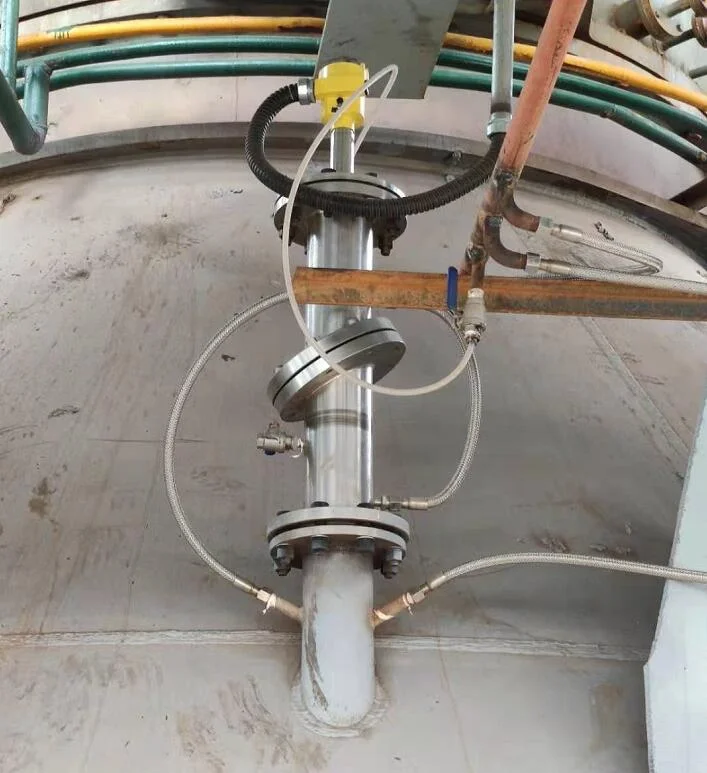
In a tank, the well is a straight pipe hung from a top nozzle, with one end above the maximum liquid level and the other submerged near the bottom. Holes of 4 to 14 mm drilled along the lower section let liquid in and out. Because the holes are small, waves and mixer-driven swirl cannot follow the liquid into the pipe; the column inside rises and falls with the true average level and nothing else.
Typical construction is 304 or 316 stainless steel for chemical service, carbon steel for hydrocarbons, and PVC only for water in atmospheric tanks. Diameters run from DN50 (2 in) on small chemical tanks to DN200 (8 in) on large crude storage. The pipe length matches the tank height plus 200 to 400 mm of extension above the transmitter mounting flange.
Why radar level transmitters need a stilling well
Non-contact radar measures the time of flight of a microwave pulse reflected off the liquid surface. Three conditions break that reflection:
- Foam. A 50 mm foam layer can scatter around 30 dB of the return signal. Low-dielectric foam on oils and surfactants is the worst case.
- Turbulence and agitators. A mixer-driven surface moves at 100 mm/s or more, and the moving echo averages into noise.
- Low dielectric constant. Liquids with a relative dielectric constant below 2.5, such as LPG, propane and vacuum gas oil, reflect only 1 to 3 percent of the signal in open-vessel mode.
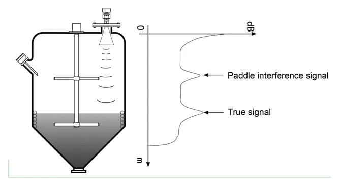
A stilling well addresses all three. The pipe shields the antenna from foam and surface motion, and it acts as a circular waveguide: the microwave energy concentrates inside the pipe and reflects off the calmer liquid column, raising the return signal by 10 to 20 dB. On LPG and similar weak reflectors, that is the difference between an unusable echo and a stable reading; a pulse radar such as our 26 GHz radar level transmitter in a properly sized well holds low single-digit millimeter accuracy.
One qualification: modern 80 GHz radar with a narrow beam can often work without a well when the only problem is internal obstructions, because the 3 to 8 degree beam threads past ladders and heating coils. Specify a well when the problem is the surface itself: foam, agitation or a weak reflection.
Which level transmitters benefit
| Transmitter type | Stilling well benefit | Required? |
|---|---|---|
| Non-contact radar (pulse / FMCW) | Waveguide effect, foam isolation | Recommended below dielectric constant 2.5 or on foaming media |
| Guided wave radar (GWR) | Mechanical protection of the probe | Optional, not needed for signal |
| Ultrasonic | Damps echo noise from turbulence | Recommended in agitated vessels |
| Float / displacer | Prevents float side-wash | Required in agitated tanks |
| Magnetostrictive | Probe protection | Optional |
| DP / hydrostatic | None; pressure taps go through the tank wall | Not used |
The pattern is simple. Anything that reads the surface from above (ultrasonic level sensors, radar) gains a cleaner echo. Anything that floats (float level sensors and switches) gains protection from side-wash and mixer currents. A guided wave radar already carries its own waveguide, the probe, so the pipe is only mechanical protection there.
Pipe sizing and hole pattern
The pipe diameter must match the radar antenna and the mounting flange. Three rules cover most designs:
- Inner diameter of 50 mm or more for horn antennas. Smaller pipes attenuate the beam.
- Antenna radial clearance of 5 to 10 mm from the pipe wall. Closer produces wall reflections; farther defeats the waveguide effect.
- Pipe straightness within 1 mm per meter. Bends scatter the pulse and bias the level reading by tens of millimeters.
The hole pattern is the second design variable. Holes that are too small respond slowly to fast filling; holes that are too large let turbulence in and defeat the damping. Industry practice:
| Pipe DN | Hole diameter | Spacing | Total open area |
|---|---|---|---|
| DN50 (2 in) | 4-6 mm | 50 mm | 2-3% of pipe wall |
| DN80 (3 in) | 5-8 mm | 75 mm | 2-3% |
| DN100 (4 in) | 6-10 mm | 100 mm | 2-4% |
| DN150 (6 in) | 8-12 mm | 100 mm | 3-4% |
| DN200 (8 in) | 10-14 mm | 150 mm | 3-5% |
Drill the holes in a staggered helical pattern, offset 60 degrees between rows, rather than straight vertical columns. The helical layout damps surface waves more evenly and avoids setting up a resonance along one side of the pipe. Match the antenna to the pipe: a DN80 horn works in a DN100 well, a DN50 horn in a DN80 well.
Installation checklist
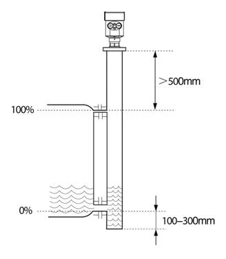
- Submersion depth. Keep the bottom of the pipe well below the lowest operating level; the inlet holes must never emerge into air during normal operation, or the column drains and the reading jumps.
- Top mounting. A welded flange on a tank nozzle is the cleanest arrangement. The transmitter bolts to the top of the nozzle flange and the pipe hangs from the same flange or rests on internal brackets. Threaded connections are acceptable on atmospheric tanks.
- Bottom support. On pipes longer than about 4 m, weld a guide ring or bracket near the bottom so tank-side flow cannot set the pipe swinging.
- Pressure equalization. Drill one 5-8 mm vent hole near the top of the pipe, above maximum level. Without it, gas trapped in the pipe as tank pressure changes will hold the column at a false level.
- Antenna alignment. The radar horn axis must be parallel to the pipe centerline within 1 degree. A tilted antenna costs several millimeters of error per meter of measuring distance.
Application example
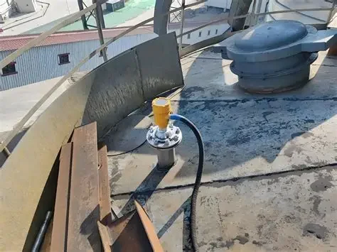
Specialty chemicals, South Asia. A producer instrumenting jacketed, agitator-stirred batch reactors asked us to cover three measurements from one process parameter sheet: Pt100 RTDs for temperature, dual-junction pH electrodes, and radar for level. Level was the hardest of the three. A stirred batch surface swirls and cones, so an open-vessel radar echo turns unstable exactly when the batch is running. This is the textbook place for a stilling well: the pipe turns the vortex into a calm column, and the radar reads cleanly through the whole batch cycle instead of only when the mixer stops.
Stilling wells in open channels and gauging stations
Hydrologists have used stilling wells far longer than tank farms have. At a river gauging station, the well is a vertical chamber set into the bank, connected to the stream through one or more small intake pipes. Waves, wind chop and floating debris stay outside; a float recorder, or today a radar or pressure sensor, tracks the calm water inside. The same arrangement serves flumes and weirs in wastewater plants, where the well sits beside the channel and isolates the level sensor from surface foam and surge.
The design logic transfers directly from the tank version: intake area small relative to well area for damping, an accessible top for the instrument, and provision for flushing because silt settles in any calm chamber. For open water and river sites we normally measure with a non-contact radar water level sensor over the well or directly over the channel; radar needs no stilling well on calm rivers, but a well still helps where wind waves or boat wash disturb the surface.
Common mistakes
- Pipe too small for the antenna. A DN40 pipe under a DN80 horn attenuates the beam by around 6 dB. Match the pipe to the antenna before anything else.
- Holes facing a mixer outlet or fill nozzle. A local jet through one hole biases the column. Position the holes 90 degrees away from any agitator outflow.
- No vent hole at the top. The trapped gas cushion makes the level reading lag the tank by tens of millimeters as pressure changes.
- A bend in the pipe. Any non-vertical section scatters the microwave pulse. Plumb the pipe vertical within 1 degree.
- PVC on hydrocarbon service. Plastic wells crack and shrink against oils and solvents over time. Use stainless or carbon steel for anything other than water.
If the tank cannot take an internal pipe at all, the alternatives are a bypass chamber outside the tank, an ultrasonic level transmitter mounted over a calm corner, or a guided wave probe. Our level instruments overview walks through the full selection by principle.
A stilling well is one of several ways to quiet an open-water measurement; for how it compares with radar, bubblers and submersible sensors on a live gauging site, see the river water level measurement guide.
FAQ
What is a stilling well?
A stilling well is a vertical pipe or chamber with small openings near the bottom, installed in a tank or beside a channel. Liquid inside reaches the same level as outside but without turbulence, foam or waves, giving a level instrument a calm surface to measure. The spelling “stillwell” usually refers to the same device.
What is the purpose of a stilling well in a tank?
It isolates the level measurement from surface disturbance. Mixers, filling jets and foam all corrupt the echo a radar or ultrasonic transmitter reads; inside the well the column stays calm. For radar there is a second purpose: the pipe acts as a waveguide and strengthens the return signal by 10 to 20 dB on low-dielectric liquids such as LPG.
What size stilling well pipe does a radar need?
Match the pipe bore to the horn antenna: a DN50 antenna fits a DN80 well, a DN80 antenna fits a DN100 well. Keep 5 to 10 mm of radial clearance between the antenna edge and the pipe wall, and keep the pipe straight within 1 mm per meter.
Can a stilling well be used with ultrasonic or float level sensors?
Yes. Ultrasonic transmitters benefit in agitated vessels because the pipe damps the echo noise; keep the pipe bore large enough to sit outside the beam-angle dead zone. Floats and displacers in stirred tanks practically require a well, otherwise mixer currents push the float sideways and the reading wanders. Displacer sizing and calibration are worked through in our displacer level transmitter guide.
Request a quote
Send the tank height, medium, operating temperature and pressure, and whether the vessel is agitated or foaming. We will size the level transmitter, and where the service calls for one, specify the stilling well dimensions and hole pattern with it. You can also reach our application engineers directly. Tell us the application and we configure one unit, not a shelf part.