By Wu Peng, Senior Process Instrumentation Engineer · Last reviewed July 14, 2026
A pressure sensor is the element that converts pressure into a small electrical signal. A pressure transducer conditions that signal into a voltage output, typically 0-5 V. A pressure transmitter converts it into a 4-20 mA current loop. A pressure switch skips the analog signal entirely and opens or closes a contact at a set pressure.
That is the working distinction. The complication is that the industry has never standardized it. Setra draws the line at load impedance, WIKA at whether the signal is amplified, TE Connectivity calls the raw millivolt device the sensor. Order by the noun alone and you can receive a voltage device for a current loop. This guide gives you the four definitions, shows where the naming actually conflicts, and ends with the one habit that makes the argument irrelevant: specify the output signal, not the noun.
Contents
- The four devices at a glance
- Pressure sensor: the sensing element
- Pressure transducer: amplified voltage output
- Pressure transmitter: the 4-20 mA current loop
- Pressure switch: a contact, not a signal
- Why vendors disagree on the names
- Choosing by output signal
- Where each fits in our range
- FAQ
The four devices at a glance
| Device | Output | Usable cable run | Typical use |
|---|---|---|---|
| Pressure sensor | Raw millivolt signal, about 2 to 3.3 mV/V, unamplified | A few meters (10 to 20 ft) | OEM boards, instruments that do their own conditioning |
| Pressure transducer | Amplified voltage: 0-5 V, 1-5 V, or ratiometric 0.5-4.5 V | Tens of meters | Test benches, data loggers, battery equipment, mobile machines |
| Pressure transmitter | 4-20 mA current loop, two-wire, often with HART | Hundreds of meters | Plant loops into PLC and DCS input cards |
| Pressure switch | Contact (relay or transistor) that trips at a setpoint | Set by contact rating, not signal | Pump protection, alarms, interlocks |
Vendor naming varies; the output column is the part to put on a purchase order.
Pressure sensor: the sensing element
Strictly, the sensor is the part that does the physics: a diaphragm that deflects under pressure, with a Wheatstone bridge of strain gauges or a piezoresistive cell reading that deflection. Its native output is small, on the order of 2 to 3.3 mV per volt of excitation for ceramic and thin-film cells. Nothing is linearized or temperature compensated yet.
That raw signal degrades within a few meters of cable, so bare sensing elements live inside other equipment: OEM boards, engine controllers, instruments that add their own electronics. Our miniature pressure sensors ship exactly this way for machine builders. In loose industry usage, though, “pressure sensor” is also the umbrella word for the whole category, which is where the naming trouble starts.
Pressure transducer: amplified voltage output
Add signal conditioning, an amplifier that linearizes the bridge output and compensates temperature, and scale the result to a voltage: now most catalogs call it a pressure transducer. Common outputs are 0-5 V, 1-5 V, and ratiometric 0.5-4.5 V, where the reading tracks the supply voltage. Voltage devices draw little current, which suits battery and solar powered equipment, and they pair naturally with data-acquisition hardware that reads volts directly.
Two limits come with the package. Voltage sags and picks up noise over distance, so plan on cable runs of tens of meters at most. And a 0-5 V signal has no live zero: zero pressure and a dead instrument both read 0 V, and nothing tells you which one you have. A 1-5 V or 0.5-4.5 V range restores that diagnostic floor.
Pressure transmitter: the 4-20 mA current loop
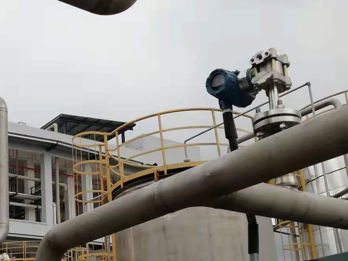
A pressure transmitter puts the same conditioned measurement on a 4-20 mA current loop, usually two-wire and loop-powered. Current does not sag with cable length, so the signal survives hundreds of meters through an electrically noisy plant. The range starts at 4 mA for a reason: a broken wire reads 0 mA, below the live zero, and the control system flags the fault instead of logging a false zero-pressure reading.
The loop math is short. A 24 V supply feeding a transmitter that needs 12 V leaves 12 V for loop resistance, so the loop tolerates up to 12 / 0.020 = 600 ohms: a 250 ohm input card plus a HART resistor plus any realistic cable still fits. Wiring details, including 3-wire and 4-wire variants, are drawn out in our pressure transducer wiring diagram guide, and the loop itself is explained in the 4-20 mA current loop guide.
Pressure switch: a contact, not a signal
A pressure switch does not report a number. It watches one threshold and changes a contact state when pressure crosses it: cut the pump at 8 bar, alarm at 2 bar, interlock the burner below 0.5 bar. Mechanical switches do this with a spring and a snap-acting contact; electronic switches such as our digital-display models add adjustable setpoints and a transistor output, and some combine a switch contact with a 4-20 mA analog output in one housing.
The specification that matters is the setpoint plus its deadband, the gap between trip and reset that stops the contact from chattering. If the process needs trend data, alarms with history, or PID control, a switch alone is the wrong device; that is measurement work, and it belongs to a transducer or transmitter feeding a controller. The full range of mechanical and electronic models is under pressure switches.
Once a switch is the answer, the next decision is contact form: whether the contacts rest closed and open on trip, or the reverse. The normally open vs normally closed guide covers which way to wire it so a broken wire fails safe.
Why vendors disagree on the names
Read three manufacturer glossaries and you get three rulebooks. Setra separates the two by electrical load: a transducer drives voltage into a high-impedance input, five thousand ohms or more, while a transmitter drives current into a low-impedance loop. WIKA draws the line at conditioning: an unamplified millivolt device is the transducer, and anything that linearizes, compensates, and amplifies is a transmitter regardless of output. TE Connectivity shifts the whole ladder down one rung: millivolt device = sensor, amplified voltage = transducer, current loop = transmitter.
All three agree on the physics and disagree only on the nouns. Instrumentation textbooks add a fourth usage, where transducer means any energy converter and transmitter means the signal-conditioning stage. Nobody is wrong; the words simply never got standardized.
The practical rule that survives every glossary: specify the output signal, the supply voltage, and the load, and the noun stops mattering. A request for “0-5 V output, 12-30 VDC supply” or “4-20 mA two-wire, HART” is unambiguous to any factory.
Choosing by output signal
| Your situation | Specify |
|---|---|
| Long run to a PLC or DCS through a noisy plant | 4-20 mA two-wire transmitter; add HART if you want remote configuration |
| Bench test, data logger, or DAQ within a few tens of meters | Voltage transducer, 0-5 V or 1-5 V; prefer a live-zero range so a dead unit is detectable |
| Battery, solar, or mobile equipment where every milliamp counts | Voltage transducer (low draw) or ratiometric 0.5-4.5 V on a shared regulated supply |
| Building the electronics yourself, high volume OEM | Bare millivolt sensor element; you own linearization and compensation |
| One action at one pressure: pump cutoff, alarm, interlock | Pressure switch; state the setpoint, deadband, and contact rating |
| Trend data plus a local trip in one device | Electronic switch with combined 4-20 mA output and switching contact |
One worked check for the long-run case. A tank farm transmitter 80 m from the control room: 80 m of ordinary 1 mm² pair adds roughly 2.7 ohms of loop resistance, negligible against the 600 ohm budget calculated above. The same 80 m on a 0-5 V line is a real problem, because every millivolt of drop and induced noise lands directly in the reading. Distance decides this one before price does.
Application example
Aerospace test facility, Germany. A propulsion team measuring liquid-oxygen pressure at cryogenic temperature sent us a specification that never used the word transducer or transmitter at all. It named the output: 0-5 V, five units, roughly 5 MPa range, AN fitting, no local display. The voltage output told us everything about the installation, short cable runs into their own data-acquisition system on a test stand, and we matched a cryogenic-rated sensor line to that output and fitting. The spec sheet that names the signal, not the noun, is the one that gets built right the first time.
Where each fits in our range
Our catalog follows the output logic rather than the naming debate. Loop-powered 4-20 mA units for plant service are under pressure transmitters; compact voltage and millivolt devices, including ceramic and silicon cells, are under pressure sensors; setpoint devices from mechanical to digital dual-setpoint are under pressure switches. Specialty builds cross the labels freely: cryogenic pressure transducers ship with either voltage or current output down to liquid-nitrogen temperature, and the SI-390 industrial line is ordered by output code, exactly as this guide recommends.
FAQ
What is the difference between a transmitter and a transducer?
In the most common usage, the output signal: a pressure transducer produces a voltage output such as 0-5 V for short cable runs, while a pressure transmitter produces a 4-20 mA current signal that travels hundreds of meters without degrading. Some vendors instead define the transducer as the unamplified millivolt device, so confirm the output signal rather than relying on the name.
What is the purpose of a pressure transducer?
To convert pressure into a usable electrical signal. The sensing diaphragm deflects, a bridge circuit turns that into millivolts, and the transducer’s electronics linearize, temperature-compensate, and amplify it into a standard voltage that a controller, logger, or DAQ can read directly.
What is the difference between a sensor and a transmitter?
The sensor is the measuring element itself, with a raw millivolt output usable only a few meters away. A transmitter packages a sensor with conditioning electronics and a 4-20 mA current output, adding a live zero at 4 mA so a failed instrument reads as a fault instead of as zero pressure.
What is the difference between a transducer and a transceiver?
They come from different fields. A transducer converts one form of energy into another, pressure into an electrical signal in our case. A transceiver is a radio term for a combined transmitter and receiver, as in Wi-Fi or walkie-talkie hardware; it has nothing to do with pressure measurement.
Name the output, and we will name the device
Send us the medium, the range, the supply voltage available, and where the signal has to go: PLC input card, data logger, or a relay that must trip at one setpoint. We will confirm whether that is a sensor element, a voltage transducer, a 4-20 mA transmitter, or a switch, and quote the matching build. Reach our application engineers or use the form below.
Written and technically reviewed by Wu Peng and the Instranova engineering team.