By Wu Peng, Senior Process Instrumentation Engineer · Last reviewed July 13, 2026
A pressure transducer wiring diagram comes down to one question: what does the output signal look like? A 4-20 mA loop-powered unit runs on 2 wires, an amplified voltage output (0-5 V, 0-10 V, 1-5 V) takes 3, and a unit with its own separate power input needs 4. This guide gives you the diagram and hookup steps for each scheme, the supply and load resistance math, the PLC side of the wiring, and a fault table for loops that read wrong or not at all.
Contents
- Which wiring scheme your transducer uses
- 2-wire wiring: the 4-20 mA loop
- Supply voltage and load resistance
- 3-wire wiring: voltage outputs
- 4-wire wiring: separate supply and signal
- 2-wire vs 3-wire vs 4-wire
- Wiring to a PLC or controller input
- Wiring faults and quick checks
- FAQ
Which wiring scheme your transducer uses
Read the output signal off the nameplate or datasheet first. The signal type sets the wire count, and everything else in the hookup follows from it.
| Output on the nameplate | Wiring scheme | Wires |
|---|---|---|
| 4-20 mA, loop powered (often marked 2-wire) | Series current loop | 2 |
| 0-5 V, 0-10 V, 1-5 V, or 0.5-4.5 V | Shared common, separate signal | 3 |
| 4-20 mA or voltage with its own AC or DC power input | Separate supply and signal pairs | 4 |
| mV/V ratiometric bridge (no amplifier) | Excitation pair plus signal pair | 4 (bridge) |
One naming note before the diagrams. The industry uses transducer and transmitter loosely; in practice a unit sold as a pressure transmitter is almost always the 2-wire 4-20 mA type, while transducer covers everything from mV bridges to 3-wire voltage units. The wiring below applies either way.
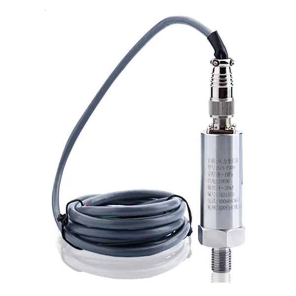
2-wire wiring: the 4-20 mA loop
A 2-wire transducer is powered by the same pair that carries the signal. The device sits in series with the supply and the receiver, and it regulates how much current flows through the loop: 4 mA at the bottom of the range, 20 mA at the top, per IEC 60381-1. Hook it up in one series ring:
- Supply positive to the transducer + terminal.
- Transducer − terminal to the receiver + input (PLC analog channel, panel meter, or a 250 ohm resistor).
- Receiver − back to the supply negative. The ring is closed; current has exactly one path.
Polarity matters. The transducer has a protection diode, so reversing the pair usually reads 0 mA rather than damaging the unit, but the loop will not work until + and − are right. Because the zero of the range is a live 4 mA, a broken wire drops the current below the signal band and the control system can tell a failure from a genuine zero reading. NAMUR NE43 formalizes this: measurement lives between 3.8 and 20.5 mA, and a compliant transmitter parks at 3.6 mA or less (fail low) or 21 mA or more (fail high) when it detects an internal fault. The full theory is in our 4-20 mA current loop guide.
HART rides on the same two wires. A HART pressure transmitter superimposes a digital signal on the 4-20 mA current, so configuration and diagnostics need no extra conductors; the loop just needs at least 250 ohms of resistance for the modem signal to develop across.
Supply voltage and load resistance
Every 2-wire loop has a voltage budget. The transducer needs a minimum voltage at its own terminals to run its electronics (12 V is a common floor for units specified 12-24 or 12-30 VDC). Whatever the supply provides above that floor is available to push 20 mA through the loads. The maximum loop resistance is:
RL max = (V supply − V min) / 0.020 A
Work one real case. A 24 VDC supply and a transmitter with a 12 V minimum give RL max = (24 − 12) / 0.020 = 600 ohms. A typical PLC input burns 250 ohms. A 500 m cable run of 18 AWG copper adds about 21 ohms (6.4 ohms per 1,000 ft, two conductors, so roughly 21 ohms per km of loop). Total: 271 ohms against a 600 ohm budget, comfortable. The same loop on a 15 V supply has only (15 − 12) / 0.020 = 150 ohms to spend and will saturate below 20 mA before full scale. When a loop reads correctly at low pressure but flattens near the top of the range, check this budget before suspecting the transducer. Our 4-20 mA calculator converts between current and engineering units when you are checking readings against a meter.
3-wire wiring: voltage outputs
A 3-wire transducer separates the supply and the signal but lets them share one common negative. The three terminals are supply + (often marked V+ or EXC), common (0 V or GND), and signal out. Wire the supply positive to V+, tie the common to both the supply negative and the receiver negative, and run the signal wire to the receiver input. The output is an amplified voltage, usually 0-5 V, 1-5 V, 0-10 V, or a ratiometric 0.5-4.5 V on compact industrial pressure transducers and OEM sensors. On cable versions the cores are color coded; a common scheme on compact transducers is brown for supply positive, green for the signal, and yellow for the supply negative, with the shield to the case. Always confirm against the label on the unit, because color codes differ between makes.
The shared common is the scheme’s weak point. Any voltage drop along that wire from the supply current adds directly to the signal the receiver sees, so keep the common short and generously sized, and land it at a single point. Voltage signals also pick up more noise than current signals over distance; keep 3-wire runs to tens of meters, use shielded cable, and move to a 4-20 mA unit when the run gets long or the route passes motor cables.
4-wire wiring: separate supply and signal
A 4-wire transducer takes power on one pair and puts the signal out on another, with the two circuits isolated from each other. This is the scheme for units that draw more current than a loop can spare: mains-powered transmitters (85-265 VAC), units with heaters or displays, and high-level outputs feeding long lines. Wire the supply pair to the marked power terminals (get AC and DC versions right; they are not interchangeable) and the signal pair to the receiver like any other analog source.
Do not confuse this with the other 4-wire scheme: the unamplified mV/V bridge. A bridge sensor also has four wires, but they are an excitation pair (typically 5 or 10 VDC) and a millivolt signal pair, and a typical 3 mV/V cell puts out only about 30 mV at full scale on 10 V excitation. That signal needs a regulated supply, short cable runs (keep them inside a panel or a test bench), and an amplifier or indicator with a bridge input. If a datasheet says mV/V, plan for signal conditioning, not for a PLC analog card.
2-wire vs 3-wire vs 4-wire
| Scheme | Signal | Cable distance | Noise immunity | Pick it when |
|---|---|---|---|---|
| 2-wire | 4-20 mA loop | Long (hundreds of m, budget permitting) | High; current is unaffected by wire resistance | Default for process plants; cheapest cabling; works with safety barriers |
| 3-wire | 0-5 V, 0-10 V, 0.5-4.5 V | Short to medium (tens of m) | Medium; drops and pickup add to signal | Machines, test rigs, OEM equipment where the controller wants voltage |
| 4-wire | mA or V, isolated | Long (current out) or medium (voltage out) | High with current output | Mains-powered units, displays, high power draw |
| 4-wire bridge | mV/V, unamplified | Very short | Low | Lab and OEM boards with their own amplifier |
Wiring to a PLC or controller input
Most PLC analog inputs accept 4-20 mA across an internal 250 ohm resistance, or 0-10 V directly; set the channel to current or voltage mode before wiring, because the terminal behavior changes with the mode. For a 2-wire transmitter on a current input: supply + to transmitter +, transmitter − to the channel input, channel common back to supply −. Several 2-wire transmitters can share one supply, each on its own channel. Check whether the card is single-ended (all channels share a common) or differential (each channel has its own pair) and follow the card manual’s grounding of the unused terminals.
When the receiver only accepts voltage, convert the current with a resistor across its input: 250 ohms turns 4-20 mA into 1-5 V, 500 ohms into 2-10 V (V = I × R). Count that resistor against the loop budget from the section above. More than one receiver can sit in the same loop in series (a panel meter plus the PLC input, for example), as long as their summed resistance stays inside that budget.
Routing rules cost nothing and prevent most noise calls. Use shielded twisted pair, ground the shield at one end only (normally the panel end), keep the signal pair out of trays that carry motor or VFD cables, and cross unavoidable power runs at 90 degrees. A floating or double-grounded shield shows up later as a reading that wanders with the plant load.
Wiring faults and quick checks
Put a multimeter in series with the loop (mA mode) or measure across the 250 ohm resistor (1-5 V) and compare against the table. Most loop problems are wiring, not electronics.
| Symptom | Likely wiring cause | Check |
|---|---|---|
| 0 mA, dead loop | Reversed polarity, open circuit, no supply | Voltage at the transducer terminals; continuity of the ring; fuse |
| Parked at 3.6 mA or lower | Transmitter fail-low signal, or supply below the minimum lift-off voltage | Terminal voltage under load vs the datasheet minimum; device diagnostics |
| Parked at 21 mA or higher | Fail-high fault signal, or process pressure over range | Range vs actual process; device diagnostics |
| Reads low and flattens near full scale | Loop resistance over budget | RL max = (V supply − V min) / 0.020; add up loads and wire resistance |
| Reading wanders with plant load | Shield grounded both ends, or signal run beside power cables | Reground the shield at one end; reroute the pair |
| Fixed offset on a voltage input | Wrong conversion resistor, or two loads where the math assumed one | Measure the actual resistance; 250 ohm gives 1-5 V, 500 ohm gives 2-10 V |
Application example
Food plant, Middle East. A processor running starch slurry and glucose lines at 85 to 140 °C needed pressure and temperature at several points, with readings back at the control room and local displays at the line. A 2-wire flush-diaphragm pressure transmitter (−1 to 2 bar) solved the wiring side: the single 24 VDC loop pair carries the power, the 4-20 mA reading, and HART configuration on the same two conductors, so each measuring point needed one twisted pair instead of separate power and signal runs, with a PT100 alongside for temperature. The wiring scheme, not the sensor, is what kept the install simple.
If you are still choosing the instrument rather than wiring one, start from the output your control system wants: 2-wire 4-20 mA for plant DCS and PLC loops, 3-wire voltage for machine controllers, and see the gauge pressure transmitters or the full pressure instruments range for units offered in each output.
Landing a 4-20 mA device on a voltage input needs a burden resistor or a converter: the values and the loop-compliance check are in convert 4-20 mA to 0-10 V.
Behind every 2-wire hookup sits a power question: what the instrument may draw from the loop and how much voltage it needs at its terminals. That side is covered in our loop-powered devices guide.
FAQ
How does a 3-wire pressure transducer work?
A 3-wire transducer powers its internal amplifier from a supply wire and puts out an amplified voltage signal (commonly 0-5 V or 0-10 V) on a separate signal wire. The third wire is a common negative shared by both the supply and the signal, which is what saves a conductor compared with a 4-wire unit. The trade is that any voltage drop on the common wire adds to the signal, so the common run must stay short.
How to wire a 3-wire transducer?
Connect the supply positive to the V+ terminal, the signal terminal to the receiver input, and the common terminal to both the supply negative and the receiver negative. Use shielded cable, ground the shield at one end, and keep the run short, since voltage signals lose accuracy over distance.
How to wire a pressure transducer to a VFD?
Most drives take a 4-20 mA or 0-10 V feedback signal on their analog input for PID pump control. For a 2-wire 4-20 mA transducer, wire the transducer + to the drive’s 24 V supply terminal and the transducer − to the analog input, then set the input to current mode (a DIP switch or parameter on most drives) and configure the PID reference. Check the drive manual for the input impedance and the exact terminal names, which differ by make.
What are the types of pressure transducer connection?
Electrically there are four: 2-wire (4-20 mA loop powered), 3-wire (amplified voltage with a shared common), 4-wire (separate power and signal pairs), and the 4-wire mV/V bridge that needs external signal conditioning. The process connection (NPT or G thread, flange, flush diaphragm) is a separate choice and does not affect the electrical scheme.
Get the wiring right at the ordering stage
Tell us the receiving system, the cable distance, and the supply you have available, and we will quote a pressure transmitter with the output that wires cleanly into it. Tell us the application and we configure one unit, not a shelf part.
Written and technically reviewed by Wu Peng and the Instranova engineering team. Based on IEC 60381-1, NAMUR NE43, and field experience wiring 4-20 mA loops and voltage-output sensors into PLC and DCS systems. Questions? Reach our application engineers.